[Editor’s note: The final installment of this three-part series on deck ledger installation addresses the connections that transfer lateral loads from the deck frame directly to the house. See Part 1 and Part 2.]
The International Residential Code has always required that any deck connected to a house be designed and built to resist lateral loads. But it wasn’t until the 2009 edition that the IRC provided a prescriptive method for meeting that requirement. Along with the design figure in the 2009 IRC, a second lateral-load figure was adopted in the 2015 IRC. While the code doesn’t specifically require that either of the designs be installed, their inclusion in the IRC raises the lateral-load-connection issue to the forefront of code officials’ minds during plan reviews and inspections.
Deck lateral-load connections resist forces—from earthquakes, from wind, from rowdy parties—that pull a deck away from the house. While a well-fastened deck ledger is capable of resisting lateral forces, that connection can fail if the ledger or house rim board is compromised by rot. A dedicated lateral-load connection transfers the loads from the deck frame directly to the frame of the house.
Like many code figures, the lateral-load-connection details in the 2009 and 2012 IRC are generic and don’t address all deck and house framing configurations. However, over the past few years, hardware manufacturers, engineered-lumber manufacturers, and industry associations have developed alternative configurations for lateral-load connections that meet the intent of the code. From the array of hardware and installation options available, deck builders just have to choose the solution that works best for the deck and house they are working on.
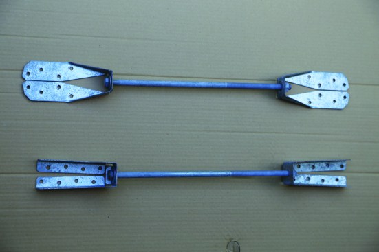
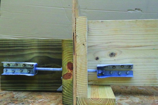
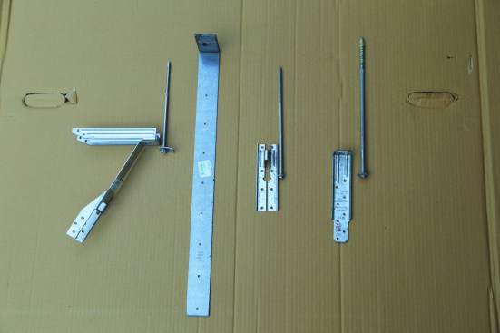
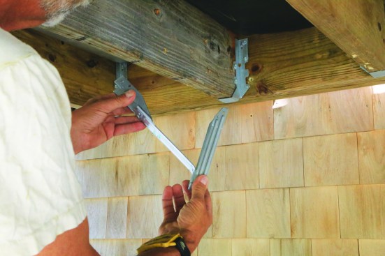
The two most common 1,500-lb. deck lateral-load ties are the Simpson Strong-Tie DTT2 (top) and the MiTek/USP DTB-TZ (bottom). Two are needed per connection, along with a 1/2-inch-diameter bolt or threaded rod, and structural screws to mount the hardware to the framing.
Two at 1,500 Pounds
The two most common 1,500-lb. deck lateral-load ties are the Simpson Strong-Tie DTT2 and the MiTek/USP DTB-TZ. Both are G-185 galvanized (the DTT2 is also available in stainless steel) and come kitted with 1 1⁄2-inch-long structural screws to mount the hardware to the side of a joist. Two are needed per connection, along with a 1⁄2-inch-diameter bolt or threaded rod.
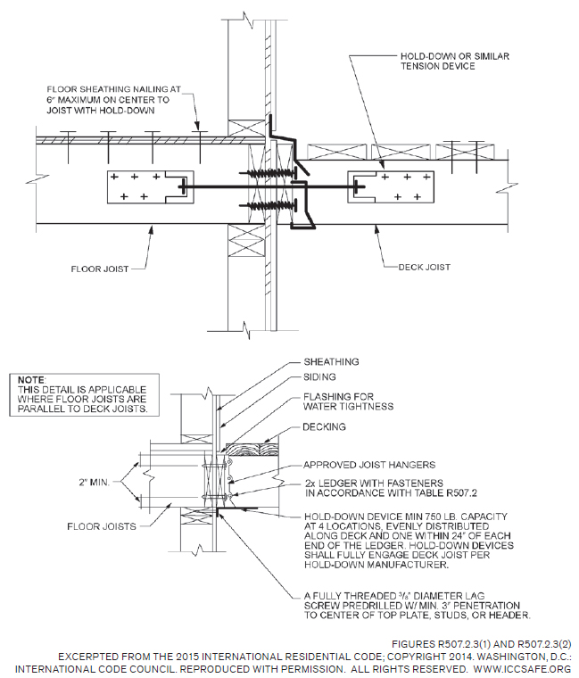
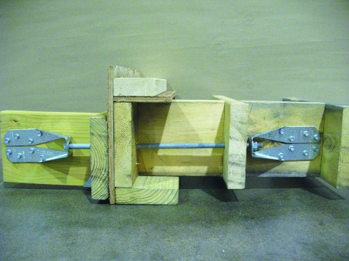
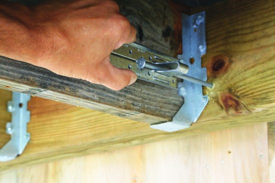
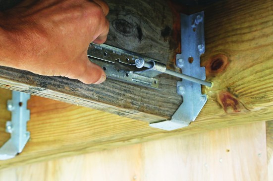
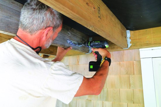
When deck and house joists are parallel, screw a metal tie to the side of a house joist and another to a deck joist with structural screws.
Drill a hole for a 1/2-inch-diameter connecting rod, and bolt the two ties together.
Installation of the two 1,500-lb. connections as shown in the code illustration is simple when the house joists run perpendicular to the rim joist of the house and there is access to the joist bays inside the house (when it’s new construction, for instance, or there is an unfinished basement or crawlspace). Simply screw a metal tie to the side of a house joist and another to a deck joist, drill a hole through the ledger and rim board for the 1⁄2-inch-diameter connecting rod, bolt the two ties together, and you’re done.
But what if a deck joist doesn’t line up with a house joist? What happens when the joists run parallel to the rim joist? How can the hardware be installed in an existing house with a finished ceiling—without cutting an access hole (and patching it later)? And what about existing homes where the nailing frequency of the subfloor sheathing can’t be verified (the IRC detail requires 6-inch-on-center subfloor nailing at the joist where the hardware is mounted)? Fortunately, there are work-arounds and solutions.
Non-aligned joists. In a worst-case scenario, deck joists that land dead center in the house joist bays would be offset by 8 inches if both the deck joists and the house joists are framed 16 inches on-center. With one tie mounted to the left side of one joist and the other tie on right side of its mate, the net difference in the position of the bolt connecting the two ties would be only 4 1⁄2 inches, given that the two opposite faces of the joists would be only 6 1⁄2 inches apart and that the bolt holes in the ties are offset by roughly one inch. If the ties are mounted on 2-by blocking fastened to the sides of the joists, the difference is narrowed down to 1 1⁄2 inches, which is within the hardware manufacturers’ allowable difference for angling the connecting rod.
Most of the time, of course, the deck and house joists aren’t half a joist bay off, in which case simply angling the rod a bit (without added blocking) may work. Alternatively, joists that align with the house frame can be added to a non-aligning deck frame.
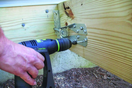
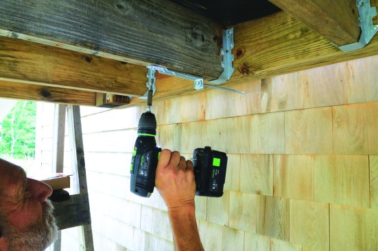
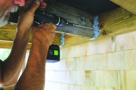
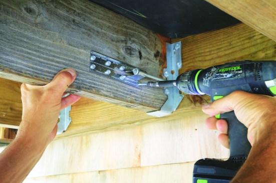
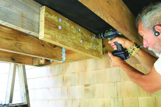
When there’s a finished ceiling, cut a hole to match the size of the planned access panel and bore the rod hole through the ledger and rim joist from the outside. A right-angle drill/driver may be needed to screw the anchor to the side of the joist.
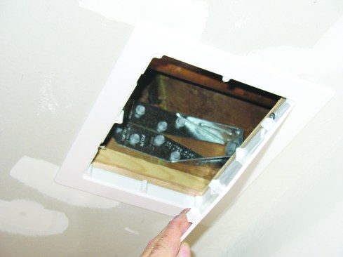
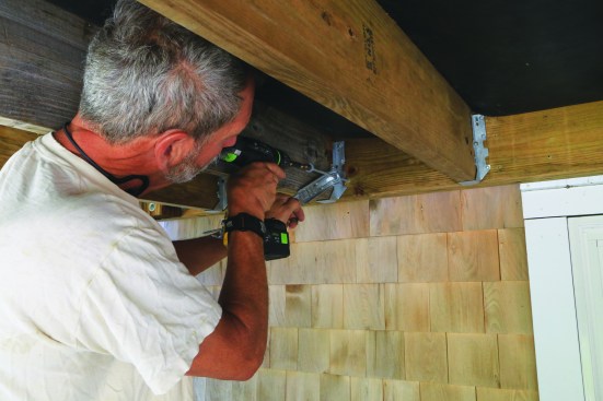
Finished ceilings. Fastening hardware to house joists is complicated when there is a finished ceiling but still manageable. I’ve installed several lateral-load anchors by cutting 6-by-9-inch access holes through the ceiling drywall alongside the joists where the hardware will be located. Removable low-profile access panels cover the holes and allow the building inspector to verify installation.
There are already plenty of utility penetrations through the ceiling of a finished basement, including HVAC registers, recessed light trims, and smoke detectors, so a couple of access panels, which can be painted to match the ceiling, don’t add much to the clutter. A false HVAC grill is another option.
If you don’t want to break through the ceiling, you can install a lateral-load anchor entirely from the outside. Before mounting the deck ledger, cut out a section of the rim joist between two joists. Reach in and fasten the tie to the joist, then double-nut a threaded rod to the tie so the rod is trapped onto the tie by the nuts. Before reinstalling the removed section of rim joist, drill a hole in it for the threaded rod. The ledger can then be installed over the rods, with the ties mounted to deck joists aligned with the rods. If you use this method, make sure to take photos before putting the rim-joist blocks back in place for confirmation at inspection that the work was done on the inside.
Existing subfloor attachment. The subfloor sheathing must be nailed at 6 inches on-center to any house joist with a 1,500-lb. tie fastened to it. This isn’t practical to verify on existing houses, so hardware manufacturer Simpson Strong-Tie offers an engineered solution that involves screwing several A35 angle brackets to the side of the house joist and the subfloor to transfer the load. You can find this detail (and several others) in SST technical bulletin T-C-DECKLAT19, “Installation Options for Deck Lateral Load Connections,” at strongtie.com.
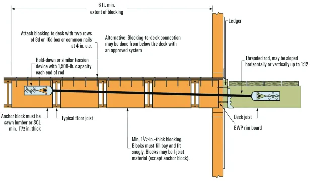
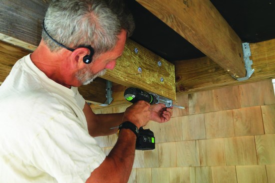
When house joists are perpendicular rather than parallel to the deck joists, solid blocking must first be installed between at least two joist bays, starting at the rim joist, then the tie must be mounted on the block furthest from the rim joist.
Joists parallel to the rim joist. Often, the house joists are perpendicular rather than parallel to the deck joists. In that case, solid blocking must first be installed between at least two joist bays, starting at the rim joist, before mounting the tie on the furthest block from the rim joist. This detail requires access to the floor joists from below to install the blocking, so it is best suited to new construction or floors with unfinished ceilings. The blocks need to be nailed through the subfloor above as well as to the joists. If there’s no access to drive nails through the subfloor, angle brackets can be screwed between the subfloor and blocks, as described above.
Attaching to a masonry wall. When the deck surface steps down below floor level, you’ll need to follow the hardware manufacturers’ minimum vertical overlap requirement (typically 4 inches) when installing the ties. If the deck ledger is fastened to the foundation wall instead of the house framing, adhesive concrete anchor rods can be connected to the ties mounted on the deck joists. Be sure to follow the manufacturer’s instructions for embedment depth and edge clearance when installing the concrete anchors to ensure they meet the 1,500-lb. load requirement.
Wood I-Joist Manufacturers Association (WIJMA)
When there is an I-joist floor system running perpendicular to the deck joists, install solid wood blocking between several inboard joists to a point at least 6 feet back into the floor system before mounting hardware.
Mounting to wood I-joists. I-joist manufacturers and the Wood I-Joist Manufacturers Association offer details for mounting 1,500-lb. ties to engineered I-joists. They all call for a 3-foot (or longer) 2×6 (or deeper) block clinch-nailed to the web; the tie can then be screwed to the block. When the I-joists run perpendicular to the deck joists, solid wood blocking must be installed between several inboard joists to a point at least 6 feet back into the floor system. Then the tie is screwed to the most inboard block and a long rod extended through the joists.
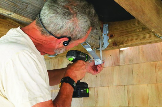
The IRC 4×750-lb. lateral-load detail is well suited for retrofits, since it doesn’t require access to the house interior; here, an SST DTT1 tie connected to a 3/8-inch lag screw embedded at least 3 inches into house framing is being fastened to the bottom of a deck joist.
Examples of hardware that meets the 750-lb. requirement include (above right, from left to right in photo) MiTek/USP ADTT, MiTek/LTS19, Simpson Strong-Tie DTT1, and FastenMaster LTS.
Four at 750 Pounds
If access to the interior framing is problematic, you might want to use the 750-lb.-tie solution introduced in the 2015 IRC. While four connections rather than two are required, all the work can be done from the exterior, so it’s ideal for building a deck on an old house or retrofitting lateral-load connections to an existing deck frame. This connection detail requires a 3⁄8-inch-diameter lag screw embedded at least 3 inches into the house framing, which can present difficulties if the deck framing and plate aren’t aligned just so. Also, the 750‑lb.-tie connections can only be installed on decks attached to the side of the house where the house joists are parallel to the deck joists and rest on the wall plate—the bearing walls of a house.
Lateral-Load Connections and Floor Trusses
The Structural Building Components Association (SBCA) has developed prescriptive designs for mounting a lateral-load connection to decks attached to open-web floor trusses using four 750-lb. ties. Where the deck is attached to the bearing wall, the detail calls for 24-inch-long gusset plates made of 7/16-inch-minimum OSB or plywood nailed to one side at the end of each of the four trusses with 10d nails spaced 3 inches on-center. The lag or structural screw is driven into the double 2-by end of the truss. Along nonbearing walls, the design calls for 2-by blocks fastened between the end truss and the first inboard truss to reinforce the vertical uprights in the end truss or for blocking installed between the top and bottom chords. You can find the detail in SBCA’s research report SRR No. 1408-01, “Deck Ledger Attachment to Residential Wood Truss Floor Systems.”
Generally speaking, 750-lb. ties can’t be fastened to the plates of nonbearing exterior walls, though it’s worth checking with your local code official regarding this limitation. There may be cases where the official will permit the use of the 750-lb.-tie option along a nonbearing wall. For example, mudsill attachment is a condition a code official may look favorably on since the mudsill is anchored to the house foundation. And in my area, the floor systems in many newer homes are framed with blocking between the first inboard joist and the rim joist along nonbearing exterior walls. These blocks are nailed through the subfloor and to the wall plate, so there’s load path continuity from the wall plate to the subfloor.
Most 750-lb. ties are available kitted in boxes of four with connector screws to mount the ties to the deck joists or blocks, and proprietary structural screws that substitute for the 3⁄8-inch lag screw that’s driven into the wall plate.
The FastenMaster LTS and Simpson Strong-Tie DTT1 ties can be installed in similar arrangements. With both, I find it easier to drive the screw into the plate or stud at the correct depth and then mount the tie to the joist or block. Unlike the code illustration that shows the short leg of the “L” in contact with the wall, the LTS and DTT1 ties can be (and usually are) installed with a space between the wall and the leg the plate screw shoulders on.
Side mount. When a deck is one step down from the level of the inside flooring, the deck ledger will be roughly centered over the wall plate. After verifying the exact position of the wall plate, drive the screw through the ledger and wall sheathing and into the plate. The tie then can be fastened to the side of the joist at the level of the wall plate.
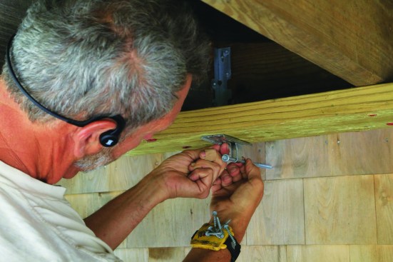
To install FastenMaster’s LTS tie, first drive the screw to the proper depth.
Next, slide the tie over the screw.
Position it on the deck joist.
Fasten the tie to the joist with the supplied structural screws.
When installing the SST DTT1, slip the plate screw through the hole in the tie before driving it to the proper depth into the house framing.
Then fasten the tie to the joist.
The LTS has a contoured knockout that allows it to be slipped over the plate screw head so the plate screw can be driven first, then the tie. When installing the DTT1, you need to slip the plate screw through the hole in the tie before driving it. The MiTek/USP LTS19 can be side mounted, but the short leg of the “L” must be in contact with the ledger.
Blocking can be installed to help align the hardware with the deck and house framing. Here, the author fastened the block to the joist with SST TimberHex HDG screws.
Then install the DTT1 tie.
Lowered block mount. On floors framed with tall I-joists, the wall plate is often lower than the bottom of the deck joists. To align the ties with the plate, I fasten 24-inch-long 2×8 or 2×10 blocking to the side of the joists with structural screws so that the bottom of the block lines up with the location of the ties.
MiTek/USP’s ADTT hardware can be adjusted to match the height of the wall plate.
The legs screw to the sides of the deck joist to form a triangle; the plate screw can be driven afterward.
The MiTek/USP ADTT has a unique design that allows it to attach to a wall plate that falls anywhere within 4 3⁄8 inches below the bottom of the deck joists. You unfold the tie and bend it to the level needed for the screw hole to match the wall plate.
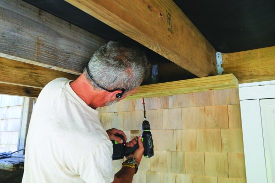
To fasten ties to wall studs rather than a plate, the author installs 2×8 blocking across the bottom of the deck joists.
The lateral-load hardware—FastenMaster LTS in this case—can then be accurately positioned for the 3/8-inch lag screws to penetrate the studs.
Stud connection. Instead of fastening the screws into a wall plate, you can drive them into the center of a stud. This option is useful when you’re attaching a stair landing that falls mid-way between floor levels. If the landing or deck joists orient squarely on studs, then the ties can be fastened to the bottom of the joists. When a stud falls between two deck joists, I fasten a 2×8 block to the underside of two adjacent joists with structural screws. The tie can be positioned along the block where it centers on the stud.
Photos by Mike Guertin