Definitions
Alternating Current (AC), standard house current, is delivered to homes by the local electric utility. It reverses direction 60 times per second in a residential circuit.
Amperage describes current flow. It’s the number of electrons per second passing a given point on the wire. To calculate the number of amps flowing through a circuit, divide the total watts by the voltage: a = w 4 v
Circuits are unbroken paths along which an electrical current flows. Each circuit forms a closed loop from the power source to the load and back.
Conductors are metal wires, usually aluminum or copper, that conduct the electricity from its source to its load.
Derated Load is the computed load of a given electrical circuit or group of circuits after it has been adjusted per the formulas given in the National Electric Code (NEC.)
Direct Current (DC) flows in one direction. Batteries supply direct current.
Electricity is the flow of electrons that takes place when a charge is created, raising the voltage potential of one point over another.
Ground is the conducting connection between an electrical circuit or an electrical device and the earth.
Loads are any appliances that use electricity, from a night-light to a central air conditioner.
Ohm’s Law is the relationship between voltage, amperage, and resistance: Voltage = Amperage x Resistance.
Resistance is a measure of how well a material conducts electricity. It’s measured in ohms. Conductors have low resistance, insulators have high resistance.
Voltage is a measure of electrical pressure or force. The greater a circuit’s voltage, the more current it will deliver to a given load. Most homes have a 240-volt service. Actual voltage fluctuates from 220 to 240 (or 110 to 120 volts).
Wattage is power consumption: the product of voltage and amperage. It’s used to estimate circuit capacity.
Watt-hours is a measure of power consumption over time. One watt-hour equals one watt of electricity used for one hour.
Codes and Standards
This guide conforms to the 2002 edition of the National Electrical Code (NEC), which serves as the U.S. electrical standard and is updated every three years.
Most local codes are based on the NEC (many are stricter). Local authorities having code jurisdiction can include state governments, municipalities, and utility companies.
Underwriters Laboratory (UL)
Most electrical equipment manufacturers submit their products to UL (or another approved testing laboratory such as ETL or Factory Mutual). The UL label certifies that a device has passed standardized safety tests. Installing an electrical device without a UL listing can result in significant liability if it causes a shock or fire.
Conductors
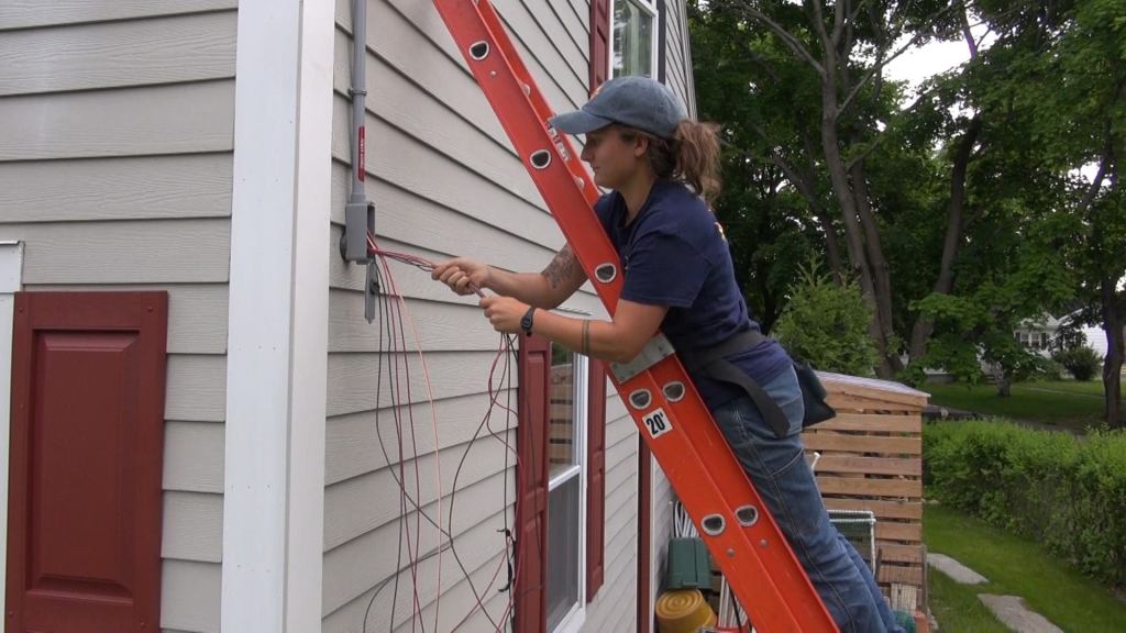
An electrical wire or “conductor” consists of one or more strands of metal wrapped in protective insulation. Wires are classified by size according to the American Wire Gauge (AWG) Standard. Most residential wiring is No. 12 or No. 14 solid copper. No. 6 and No. 8 copper and aluminum are used for large appliances, and No. 4 and larger stranded copper and aluminum wires are used for main service entrances (below).
Ampacity
The ampacity of a conductor is its current-carrying capacity, which is a direct function of wire gauge. The 14-gauge and 12-gauge wire used in most residential branch circuits can handle a maximum of 15 and 20 amps, respectively. Large appliances, such as stoves and dryers, use larger diameter wires. Exceeding a wire’s ampacity can lead to the overheating of conductors and may cause a fire. The maximum ampacity and circuit breaker size allowed for common conductor sizes is shown in the figure below.
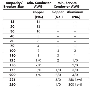
Note: Entrances of 50 ft. and longer may require larger conductors to compensate for voltage drop.
Wiring in branch circuits should be sized so the voltage drop does not exceed 3% from the panel to the farthest load (Maximum Recommended Length of Branch Circuits, below). Exceeding these runs can make devices run less efficiently and puts stress on motors. Voltage drop will also cause the conductors to heat up slightly and will waste electricity. This can be a concern for long service entrance conductors. If the meter is installed remote from the house, a customer will be paying for the electricity consumed by voltage drop. Studies have shown it is cost effective to upsize service entrance conductors to alleviate voltage drop. The added cost of the conductors will be offset by savings in the electric bill.
Aluminum Service
- Pros: The chief benefits of aluminum conductors are twofold: aluminum is lighter in weight than copper and less expensive. For these reasons, aluminum has become popular for service entrances.
- Cons: Because aluminum doesn’t conduct as well as copper, especially at high temperatures, aluminum wiring must be larger than copper at a given ampacity.
When large conductors are bent to reach terminal lugs, aluminum has a much greater tendency to spring back, increasing the difficulty in terminating it.
If aluminum connectors are not coated with grease or an antioxidant, they will oxidize rapidly and become coated in a flaky, whitish powder.
The biggest problem with aluminum is its high coefficient of expansion. The expansion and contraction of an aluminum wire can loosen a badly made connection. Since the resistance of a loose connection generates heat, this can lead to a fire.
When properly installed, aluminum wiring is safe. When terminating, you must coat the connections with an appropriate aluminum grease or antioxidant and properly tighten each fitting and/or lug. It is also recommended to check connections and tighten as required every year or two. Some municipalities require service entrance conductors to be copper. This is common in coastal cities where the salt air may corrode aluminum conductors. Many electricians prefer to use copper wires for services because it is easier to work with, and the savings in time using copper wires can offset the added cost of copper conductors.
Cable
A cable consists of two or more insulated wires spiral-wound together inside a single protective sheath. A cable’s capacity is determined by the ampacity of its wires. How and where a cable can be used is determined by its sheathing. Letter codes on the sheathing indicate the type of insulation, its maximum temperature rating, and whether the cable can be used in wet or dry installations. Common residential cable types are described in the figure below.
Wire Insulation Color Codes
The wires in a cable are color-coded according to their intended use (below). Grounded neutral conductors are white. Grounding wires are either bare or green. All other colors denote hot wires: black for two-wire (120-volt) cable, black and red for three-wire (240-volt) cable.
Conduit
Use conduit where there’s a serious risk of damage to conductors, such as underground runs beneath driveways or slabs and through the building shell. Some codes require conduit for all installations, others for block and poured concrete buildings. Conduit is installed empty and the wires are pulled through it later.
Conduit is used primarily for individual conductors rather than cables. The number of conductors allowed depends upon wire size, insulation type, and the cross-sectional area of the conduit.
The choice of conduit will depend on local codes:
Rigid steel is a heavy-walled galvanized conduit that shares the same thread and diameter sizing with plumbers’ black iron pipe. It is available in 10-ft. lengths in sizes from 1/2 in. to 4 in. and sometimes larger. Use it for underground or under-slab installations or in places exposed to severe weather or mechanical abuse.
Electrical Metallic Tubing (EMT), or Thinwall®, is a lighter-duty conduit commonly used in residential work. It’s easier to work with than rigid steel, and is appropriate for less abused runs, such as those from a meter to an exterior panel or from an underground service to a meter.
Flexible Metal Conduit, or Greenfield®, resembles a BX sheathing without the wires. It is useful for connections to vibrating equipment.
PVC (polyvinyl chloride) conduit is impervious to water and oil, and to damage from sunlight or pollution. It is available with a wall thickness of Schedule 40 or Schedule 80, and comes in 10- and 20-ft. lengths that are joined with PVC cement. It is commonly used for underground and under-slab installations that do not require rigid steel. Much lighter and less expensive than steel, it can be bent by heating it with special PVC benders and connected using a wide variety of glue-on fittings. PVC pipe is also common for protecting service entrance conductors. It is easy to use and will not corrode when exposed to the elements. Since PVC is not conductive, it does not need to be grounded. The requirements for grounding metal pipe in a service are complicated and costly, so the savings can be dramatic if PVC is used.
Sealtight®, or Liquidtight®, is a flexible PVC conduit that provides a moisture-resistant flexible connection for the operation of equipment in damp locations. This product is available in two types, one that is all plastic and another that has a spiraled metal jacket within the outer PVC coating.
Bending Radius and Conductor Fill
Both the length of the run and the number of bends affect the difficulty of pulling conductors through a run of conduit. Code dictates that no single bend shall be greater than 90 degrees, and the combined angle of bends between any two pulling points in a conduit run shall not be more than 360 degrees (four right angles or equivalent).
The code also limits how many conductors can go through a given size conduit. The figure below gives the minimum conduit size when all wires are the same gauge.
Surface Raceways
In remodeling, surface-mounted raceways are often suggested as an alternative to fishing wires through existing walls, since this is faster and leaves conductors accessible at all points. They also may be recommended as an inexpensive option by weatherization contractors who are installing fans or by electricians who are retrofitting hard-wired smoke detectors. However, in custom work, the appearance of a raceway is rarely acceptable. Use them only in utility areas or in areas where future wiring changes are expected. Most manufacturers of surface raceway offer prefinished products, but you can also paint a raceway to match the room trim. Like conduit systems, surface-mounted raceways are installed empty and individual conductors are pulled through.
Boxes
All wire connections — switches, receptacles, lights, and junctions — must be made within code-approved boxes.
Cutout Dimensions
“Standard” 1-gang metal device boxes measure 3 in. high and 2 in. wide, but require a minimum 33/8×21/8-in. cutout; 2-gang metal device boxes typically call for a cutout that is 33/8 in. high and 41/8 in. wide. Plastic boxes often require slightly larger cutouts, depending on the reinforcing fins.
Conductors Per Box
The number of conductors that can be packed into a given box depends on the box’s volume (volume is stamped on the box). Box depth varies. Typical metal 3×2-in. metal device boxes typically have volumes as follows:
11/2 in. deep = 7.5 cu. in.
2 in. deep = 10 cu. in.
21/2 in. deep = 12.5 cu. in.
31/2 in. deep = 18 cu. in.
In general, use the largest box possible. Shallow boxes (11/2 in. deep) often can’t be used for anything but a switch. The figure below gives the maximum number of equally sized conductors per box, without connections or devices. Adjust these numbers for boxes with different size conductors, connections, and devices as described in the figure notes (count receptacles and switches as two, clamps as one, etc.).
Temporary Service
New construction often requires a temporary electrical service to provide a location for circuit breakers and metering equipment during construction.
Temporary service is usually rated at 100 amps and, like the permanent variety, can be either overhead or underground. Most utility companies will not run an overhead entrance cable more than 100 ft. from a utility pole. If the attachment is overhead, a cable or conduit riser must be run up a suitable pole or post to the minimum attachment height allowed by the electric utility (below).
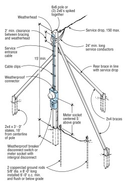
Temporary power pole specs are often enforced by the utility that supplies the power. The required double mast protection — conduit and wood covering — may seem extreme until the first time a backhoe slams into the pole. Extend the pole’s height to 18 ft. if it is installed over any areas that receive motor vehicle traffic.
Enclosures for meters and circuit breakers must be rated as weatherproof. Units with both the metering and distribution panel in the same box save time in field assembly. Temporary services must be grounded at the enclosure that holds the main disconnect breaker or fuses. Two 8-ft. ground rods, 6 ft. apart, must be driven into the ground and connected to the service’s grounding terminal with a No. 6 copper ground wire. The ground wire must be attached to the ground rod with a clamp designed for that purpose.
GFCI Protection
Branch circuits for temporary construction power must be GFCI protected. This may be accomplished in one of two ways: by using GFCI circuit breakers in the distribution panel to feed these circuits, or by installing GFCI receptacles wherever workers are able to plug in for temporary power.
Temporary Lighting
As the building gets closed in, temporary lighting may be needed. The NEC no longer allows field-fabricated strings of temporary lights. If using cords bearing multiple pigtail-type sockets, they must be part of a listed assembly with no wire-nut connections. To protect the lamps from combustibles and damage, use fixture sockets with plastic cages.
Inspecting Existing Service
Before starting a remodel or addition, take a close look at the existing service. This includes the rated service capacity and the condition of the house wiring and service panel.
Service Capacity
Many older homes have 30- or 60-amp services. But today’s homes need at least 100 amps. Some electricians install 200-amp systems as a matter of course, just to cover any future additions to the electrical load.
Wiring Condition
Check out the existing wiring (look in the basement, the attic, and in several wall boxes). Look for damaged, brittle, or crumbling insulation, improperly made splices, or rusted conduit or cable armor. These are all signs that the wiring needs to be replaced.
Also inspect the service ground. If a ground connection is corroded, it should be replaced.
Service Panel
If the main panel is a 60-amp fuse box, don’t add to it, as this will risk overloading the system. Even larger fuse boxes should be inspected carefully.
Breaker panels have a different problem: one manufacturer’s panel won’t usually accept another’s breakers. Even if the breakers from a different company fit a panel, they usually cannot be used legally. If the manufacturer has gone out of business, its breakers may be hard to find and expensive. If you need a lot of them, consider buying a new panel.
Regardless of panel type, look for the following problems:
- A full box. Is there room for more circuits? Look for empty slots or screws and use a voltage meter to check for full voltage.
- Overfusing. A 30-amp breaker or fuse in a 20-amp circuit (wired with 12-gauge wire) is a serious fire hazard. Replace with the proper size fuse or circuit breaker.
- Heat damage. Can you see discoloration in the box or hot spots that have melted and solidified? Pull the main fuses or breakers and check the contacts or prongs for overheating.
- Damage to the hot bus. Arcing from loose breakers can burn and deform the busbar along the back of the panel that the circuit breakers plug or screw onto. This damage can make it impossible or inadvisable to replace a circuit breaker with a new one.
- Corrosion. If the panel is rusty or corroded, the breakers may be also. Corroded breakers may not trip. That can lead to a fire. If you find a corroded panel, fix the moisture problem that caused it. A corroded main disconnect may indicate a poor weather seal where the service penetrates the building shell.
Extending Existing Circuits
When tying into existing circuits, remember the following:
Grounding
In an ungrounded system, all new wiring should run back to the main panel, which must be grounded. Do not extend an existing ungrounded 2-wire circuit with grounded wiring and devices. This is unsafe and it is a code violation.
Overloading
As a rule of thumb, don’t put more than 10 duplex receptacles on a general-use branch circuit. To be certain that you are not overloading an existing circuit by extending it, add up the wattage of all appliances and lights on the circuit that might be used simultaneously. If the circuit is already near capacity, don’t extend it.
Wire Gauge
Also make sure that the wire you are planning to tap into is properly sized. When wiring a 20-amp circuit, for instance, make sure that the old wiring is not 15-amp (14-gauge wire).
Wiring Methods
It is permissible to fish NM and AC cable through hollow wall spaces when rewiring or extending existing circuits. In this instance, you are not required to staple or strap the cable at the usual distances required in new construction.
Special steel or nonmetallic devices and fixture boxes (often referred to as “old work boxes”) may be cut into existing wall and ceiling surfaces. These boxes are manufactured with “ears” that support the box against the wall or ceiling surface and prevent it from falling through the hole that is cut for it.
Boxes may be fastened with screws through holes provided in the ears if there is anything substantial, such as wood lath, to screw into behind the box. In situations where the box is cut into a drywall surface, “Madison straps” (thin, shaped, metal strips) are slipped into the wall past the sides of the box and their tabs are folded into the box, securing it to the wall.
Many electricians choose to tape up the sides of any devices installed in a box supported by Madison straps. The metal tabs that are folded into the box may cause a short circuit if they come into contact with a device’s termination screws.
Testing Devices
Almost all problems with electrical circuits have to do with overloaded circuits, open circuits, or short circuits. With overloaded circuits, the only thing that can be done is to limit the existing load or add a new circuit to feed part of that overloaded circuit. An open circuit is one where the hot wire or the neutral is failing to make a connection to allow the voltage to travel from the circuit breaker, through the circuit, and back to the neutral bar. A short circuit is when the hot wire (or a live portion of a fixture or device) is coming into contact with a neutral or ground wire or a grounded box or appliance case, and it (hopefully) is tripping the circuit breaker.
Most electrical problems can be traced with a tester as long as the problem is active. An intermittent short or open circuit — if not active — will often leave no trace, and the troubleshooter’s only recourse is to examine all of the devices and junction boxes in the problem circuit, and try to discover the problem through a visual inspection. Look for loose connections on devices and in wire nuts or damaged insulation on the wires in boxes.
A receptacle analyzer, a voltage tester, and a continuity tester are all you’ll need to diagnose most residential electrical problems. A multitester will do everything these tools will, plus more detailed tests.
Receptacle Analyzer
The plug-in receptacle analyzer is an inexpensive tool that checks polarity and grounding. It looks for open ground wires, open neutral wires, open hot wires, reversed hot and ground wires, and reversed hot and neutral wires. This device is simply plugged into an outlet and will display a combination of lights upon its face. Each comes with its own individual directions for interpreting the display lights it generates. Use it to diagnose wiring problems such as reversed polarity, open neutrals, or missing grounds (Receptacle Wiring Problems, below). These wiring problems can all be detected with a plug-in tester.
Neon-Voltage Tester
The neon-voltage tester consists of a small bulb and two leads. It’s used to check for live circuits, and to test polarity and grounding. You can use the neon tester on receptacles, lights, switches, and in the distribution box itself. Although this device has been used successfully for years, it is limited in comparison to, and is not as reliable as, the multitester.
Voltage. To check a receptacle for voltage, insert one lead of the neon tester into each receptacle slot. If the bulb glows, the circuit is hot. If not, it probably isn’t. But remove the cover plate and re-test at the screw terminals just in case.
Ground and polarity. In a properly wired receptacle (or any other device), the tester will glow only when placed between the hot and neutral, or hot and ground, leads. If it glows between the neutral and ground leads, then the receptacle’s polarity is reversed. Rewire it. If the tester doesn’t light between either of the leads and ground, then it’s not grounded.
Finding the hot wire. Place the tester between each wire and ground (in an ungrounded system, use a known neutral, such as the side of a metal box or a water pipe, as your reference). The hot wire will make the bulb glow.
Testing switches. If a switch is getting voltage, the tester will glow when placed between its bottom screw terminal and ground or between the bottom terminal and neutral in an ungrounded system. If the switch itself is working, the tester will glow when placed between the top terminal and ground with the switch on.
Testing fixtures. Place the tester between the hot and ground, or between the hot and neutral. It should glow when you turn on the switch.
The Multitester
The multitester (also called a multimeter or a volt-ohm-meter) measures voltage, current, and resistance. It works on both AC and DC circuits. Multitesters have either analog or digital readouts. For household circuits, choose one that measures up to 250 volts AC and includes RX1, RX10, and RX100 settings to test resistance.
Voltage tests. While the neon-voltage tester is a simple on-off indicator, the multitester measures voltage levels. Use it for voltage tests as described for the neon tester. Instead of seeing a simple lamp glowing, an actual reading is given of the voltage present at that point in the circuit. This can be useful, for example, when analyzing a distribution panel, where reduced voltage at the screw terminals may indicate loose or corroded connections.
Transformers. To test a low-voltage transformer (which doesn’t supply enough power to light a neon tester), make sure that there’s power going to the circuit. With the multitester set to the 50-volt range in the ACV scale, touch the probes to the transformer’s terminals. If it registers zero voltage, then the transformer is dead.
Continuity. The multitester’s resistance (ohm-meter) scale is used to verify if a circuit is continuous from one point to another. This can indicate whether or not a switch is allowing voltage through in the “on” position, whether a fuse is blown or not, and whether the filaments in an incandescent lamp are burned out. Before trusting the reading from a continuity tester, short the leads of the tester together and be sure that you get a reading of continuity (no resistance.) This function depends upon a tester’s internal battery, which needs to be replaced from time to time.
Troubleshooting Circuits
If a series of outlets is not working, there are two common problems to explore. If the problem seems localized to a small area of the house, the problem is usually a connection gone bad — either back-wiring gone bad or a bad splice. If the problem is more random and seems to be roughly half the house, the problem is probably at the service. Check to be sure both hot feeds are energized. The problem is almost never “buried someplace in the wall” as many people claim.
Testing for Shorts
The first step in finding a short circuit is to check all receptacles, outlets, and fixtures on the affected circuit. Look for loose or bare hot wires that come in contact with neutral wires or boxes. Also look for over-tightened cable clamps that may have cut through wire insulation.
To find a short, unplug all appliances, reset the breaker, and turn on the lights. If the breaker doesn’t trip, the problem is in one of the appliances. If it does trip, test the branch circuit itself.
To isolate circuit problems, disconnect the wires somewhere in the middle of the circuit. If the circuit still trips, the short circuit is located before this connection. If the circuit does not trip, the short circuit occurred beyond this point. Reconnect the wires and move on to another box. Be sure to record the results on a rough drawing of the box layout. Eventually, the right box will be located and the problem can be fixed. Also check for obvious black spots in the box. Short circuits often leave a mark.
If the short is located between boxes, test each section of cable for a short between the hot wire and the ground and neutral with a continuity tester until you have located each end of the shorted cable.
If no shorts are present, there should be resistance between all of the wires. If a section of cable appears to be shorted somewhere between boxes, usually the only option is to replace that section of cable.


