Switches
Switches should always be wired on a circuit’s hot side — that is, they are only connected to the black wire and rarely connected to the white wire. When necessary, it is permissible to use the white conductor as a hot wire. However, the white wire must be re-identified with black paint at both ends in the switch and fixture boxes so that it does not become confused with the other white wires that are neutral conductors. Some inspectors do not consider tape permanent enough to use as a marker.
Newer switches also have a grounding terminal. When replacing an older switch with a new one, the replacement should match the amperage and voltage ratings of the old switch. It should also be rated for the particular circuit’s wire gauge. Ratings are stamped on the switch (Reading a Switch, below). Common types of residential switches are shown in Common Types of Residential Switches, below.
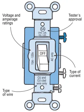
Switches are rated for a particular wire type and maximum amperage. When using aluminum wiring, use only switches marked CO/ALR, which are safe with either copper or solid aluminum wiring.
Single-pole switches have a single set of contacts that are either open or closed, depending upon the position of the switch. This switch controls a fixture or receptacle from only one location (below).
Three-way switches flip a conducting lever back and forth between two connection points called travelers. These control a lighting load from two locations (below).
Four-way switches. If a group of lights needs to be controlled from more than two locations, any number of four-way switches may be wired into the circuit in between the two three-way switches. In these switches, there are two hinged conducting levers that swap the power back and forth from two load screws. In a four-way switch, the traveler wires from one three-way are connected on one end, and the traveler wires to the next four-way (or the end three-way) are connected on the other (below).
Combination switches can include any combination of switches, outlets, and indicator lights. Some combination switches require a jumper between the various parts. If so, the gauge of the jumper should match that of the circuit wire.
Dimmer switches are designed for lights, not for appliances such as ceiling fans, which need special variable-speed switches. Fluorescents require special dimmer switches that will not work unless the light fixture is equipped with a dimming ballast.
A dimmer’s wattage rating should meet or exceed the combined wattage of the lights the dimmer controls, or it will overheat, creating a fire hazard. Standard, low-cost dimmers can handle only 600 watts, restricting them to no more than four 150-watt bulbs. This becomes problematic with track lighting units where any number of lights might eventually be installed. Many electricians use dimmers rated for 1,000 watts or more when installing track lighting. These include an external heat sink to dissipate excess heat.
Receptacles
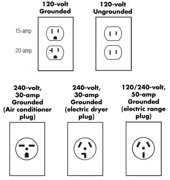
Receptacles can be designed to receive only one cord end (simplex) or two (duplex). They also are available in several amperage ratings and slot configurations (below).
Duplex Receptacles
Fasten the hot wires (black) to the brass screws, and fasten the neutral wires (white) to the silver ones. The green grounding screw is connected to the cable’s grounding wire and to the outlet box, if it’s metal. Receptacles are rated and stamped like switches.
Many modern receptacles (and switches) have push-in “back-wire” connections that can be used instead of the screw terminals with solid-wire. Back-wire connections are not recommended. Backwiring is a common cause of circuit failures in homes. The connections heat up and fail over time, and may even cause a fire.
Polarity
Newer polarized receptacles have one long and one short slot. The hot wire feeds the short slot and the neutral wire feeds the long slot. A polarized appliance has a plug that fits the receptacle only one way.
Getting polarity right is crucial. If a polarized plug is wired incorrectly, current may flow to the metal cabinet of a polarized appliance — a dangerous shock risk. Check polarity with a multi-tester, a plug-in circuit analyzer, or a neon tester (see Testing Devices).
Receptacle Orientation
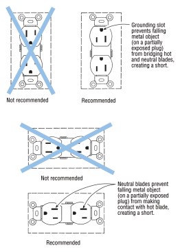
Although it’s not a code requirement, many electricians orient receptacles so that if a metal object (such as a loose metal cover late) falls while something is plugged in, it will land on the plug’s neutral or grounding prong, rather than on the hot one (below).
Split Receptacles
A break-off tab between the two hot terminal screws allows a receptacle to be split so that each socket serves a different branch of a multi-wire circuit. In rooms (other than kitchen and bath) without a hard-wired fixture, split receptacles are commonly used to switch one-half of a duplex receptacle (below). They can also be used with 3-wire cable to power two separate circuits that share a neutral, although this is less common in residential wiring.
Wall Plate Dimensions
Wall plates for both switches and receptacles are available in three sizes — standard, midway, and oversize (below). No matter which plate you use, the wallboard or plaster must be within 1/8 in. of the box. If the space exceeds 1/8 in., it is the electrician’s responsibility to have the gaps repaired.
Switch Locations
Rooms and hallways, as well as exterior entrances and walkways, should be well illuminated. For information on locating light fixtures.
For locating switch boxes, follow these general guidelines:
- Locate light switches where a room is entered. In rooms with more than one entrance, use three-way or four-way switches (see Switches, above).
- Keep switch boxes at a consistent height from room to room. While many electricians center their switch boxes at 48 in. from the floor, 42 in. is often more comfortable for clients.
- Never locate the switches behind the door swing.
- In rooms where primary lighting is provided from lamps plugged into receptacles, switches at the entrances to the room must control all or half of at least one receptacle (see figure, Partially Switched Receptacles, above).
Exterior Wiring
Entrance Lighting: By code, all grade-level entrances to the house must be illuminated by a switched light (below). While exterior lights are not required for a balcony or elevated deck with no ground-level access, many customers may still want one.
Exterior Outlets: Open porches do not count in calculating the house load, but specific codes may apply to special applications. Electrical service on an open porch or deck must have GFCI protection. Verify that the branch circuit the receptacle taps into doesn’t exceed the maximum number of allowed receptacle outlets, and that the house wiring is grounded and in good condition.
Garages: General-purpose outlets in garages and detached shops or sheds must be GFCI protected. Dedicated receptacle outlets, such as those for garage door openers, freezers, refrigerators, fans, etc., are exempt; standard grounded outlets may be used here.
GFCIs
A ground-fault circuit interrupter, or GFCI, is a special-purpose circuit breaker. It is not tripped by a current surge or overload, but by a difference in amperage between the hot and neutral wires. Such a difference can be caused by leaking to ground (for example, when someone standing on a wet floor touches a short-circuited toaster). GFCIs sometimes trip due to fluorescent lighting loads or with some electric motors.
There are two types of GFCIs: circuit breakers that are installed in the distribution panel, and individual receptacles.
GFCI receptacles are less expensive than the circuit breakers, and they protect only those appliances plugged into that receptacle and those plugged into downstream receptacles. A GFCI circuit breaker protects every appliance plugged into the circuit.
All outdoor receptacles must be GFCI-protected.
GFCI Locations
The code requires GFCI-protected receptacles in any potentially wet area (below). That includes all kitchen countertops, and in bathrooms, garages, unfinished basements, crawlspaces, and outbuildings (except as noted below).
An exception to the areas above include a dedicated outlet for a refrigerator or freezer, since these appliances may trip a GFCI when there’s no danger of shock (and spoil the food). Also, GFCIs will not work with any appliance that has a ground wire connected to its case, such as ranges, cooktops, and clothes dryers. In addition, GFCIs should not be used with medical equipment, sump pumps, or any other critical equipment that must operate in an emergency.
If one of these excluded appliances is located where GFCI protection is generally required, such as in an unfinished basement, then install a single (not duplex) receptacle just for that appliance.
In general, lights should never be on a GFCI circuit, since loss of lighting could be a safety hazard. One exception to this rule is a light or fan/light installed in a shower stall or directly above a tub/shower unit.
The NEC requires bathroom receptacles to be fed off a dedicated 20-amp branch circuit. You can use this circuit to feed other items in the bathroom if two rules are followed: The receptacle circuit cannot be used to feed any other rooms, and the connected load of all of the fixed equipment except the lighting cannot exceed 10 amps (below). Check with the local code to make sure it matches the NEC on this.
GFCI Limitations
A GFCI guards against current leakage only. It won’t shut down an overloaded circuit, and it offers no protection if a person contacts both the hot and the neutral side of the circuit at the same time.
For example, if a person were standing on a non-conductive surface such as a dry wood floor and touched both the black and white wires, the electricity would flow out the black wire, through his body, and would return through the white wire. No current would leak to ground, so no “ground-fault” would be detected. Similarly, a child who sticks two screwdrivers into either side of an outlet will not be protected.
A GFCI-protected circuit still needs properly sized over-current protection; and it should be treated with the same respect as any other part of the electrical system. GFCI receptacles must also be sized to match the wiring. Never use a 20-amp GFCI receptacle on circuits with 14-gauge cable. A horizontal slot off the wide prong indicates that a GFCI is rated at 20 amps.
GFCI Testing
Every GFCI has a test button on its face. Homeowners should be told to test them every month.
Wiring GFCI Receptacles
A GFCI receptacle can be used to protect all downstream outlets (below). Such feed-through protection is less expensive than putting a GFCI on every outlet, but it makes ground-faults harder to locate and fix. When a feed-through GFCI trips, the problem could be with the GFCI itself or with any wiring downstream.
GFCIs in Ungrounded Systems
A GFCI will work in an ungrounded circuit but it cannot be tested. The test button will always indicate that the device is not working.
When using an ungrounded GFCI for feed-through protection, don’t connect the green grounding screw to any downstream receptacles. Someone may later assume that the receptacle is properly grounded — a potentially deadly misunderstanding.


