We were recently contracted to replace a “walk-into” bay window in a house built during the late 1970s. Unlike smaller bay windows that hang from a cable system or that are supported by brackets, these bays have floors that are either cantilevered or, as was the case in our project, supported by a full foundation.
The bay was quite large—about 9 feet wide and 7 feet tall without the roof—and a nearby privacy fence and mature landscaping would have made it almost impossible to bring in and install a stock unit without doing some damage. And although the existing bay window was likely a stock size back in its day, the closest available size we could find was about an inch too wide—close, but not ideal. Our solution—one that we’ve used in the past when remodeling bay windows—was to fabricate the components in our shop and then truck the bay window to the jobsite in manageable pieces for assembly there.
We began by measuring the existing bay and ordering three new windows. While we opted for Marvin Clad Ultimate Double Hung units for this project, almost any good-quality double-hung window would have worked. The windows themselves were stock, except for the code-required tempered glass for the lower glazing that would be just above the finished floor.

Sue Burnet
The windows, roofing, walls, and roof structure were torn out of…
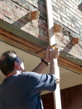
Tearout & templating
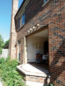
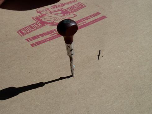
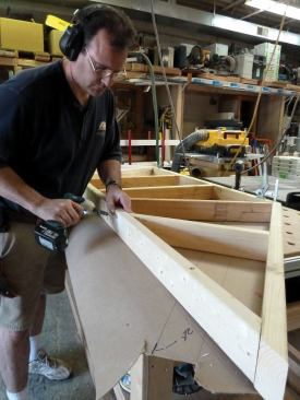
After taking delivery of the windows, we turned to construction—or demolition, to be more precise. We tore down the existing bay, removing the windows, roofing, walls, and roof structure, and leaving only the floor and the sole plates in place. The floor for this bay was structurally sound and the finish flooring was in good shape, so we protected it with a layer of Builder Board for the duration of the project.
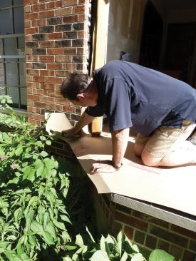
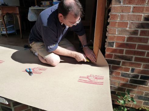
Once we had finished the demolition, we made a template with a second piece of Builder Board, spreading the paper board over the floor in the opening and folding it to mark the location of the limestone sills. We indexed the template by cutting in the corners of the house walls and marked the outline of the plates by poking through the template with an awl. Two poked holes along each wall served as dots we could connect to create a full-scale “plan” for accurately laying out and framing the roof and wall components. We also made a story pole marking the height and width of the opening, and clearly labeled each critical reference on the story pole and the template. With the bay foundation and opening templated and measured, we tarped the opening and headed to the shop.
A different approach to framing
The most challenging part of a bay window to frame is its faceted roof. My approach used to involve scaffolding and countless trips up and down ladders as I muddled through the cut-and-fit process. But then I realized that most bay roofs are small enough to frame on the ground and safely lift into place, saving time, sanity, and wear and tear on my knees. So now we fabricate the roof and other components in the shop, where my tools are all set up and we can contain most of the mess. We also don’t have to worry about the weather.
For those of you looking for a lesson in classic roof framing, suspend your expectations for a moment. The strategy I use to build a bay-window roof bases all the framing on the template. The parts of the frame in one of my bay roofs are hybrid applications of familiar roof framing parts, but they work in the same way. I will explain the differences as I go along.
My strategy also allows me to modify the original roof if need be. For example, the demise of the windows in the existing bay was mostly due to the drip line of the roof not extending beyond the perimeter of the limestone sills below. Precipitation dripped off the roof onto the sills and splashed onto the windows, eventually causing them to fail. When I made my template, I included the outer edge of the limestone sills. Then when I laid out the roof, I made sure that the drip line would fall outside of that perimeter.
The final advantages to this system are speed and efficiency. This strategy is a production approach to what can be a difficult framing challenge. Because all my figuring is based on the template, which is a full-scale plan of the frame, the complicated geometry is already done for me.
Layout in the shop
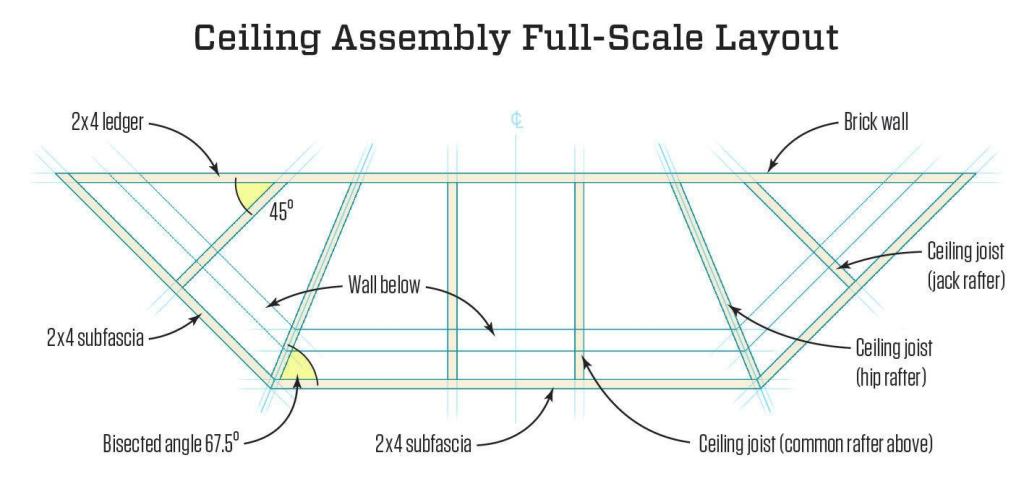
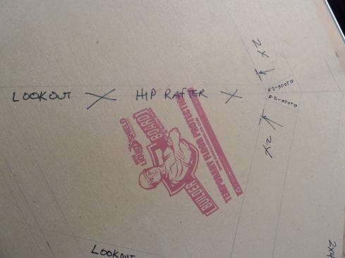
At the shop, I unrolled the template and clamped it to a workbench. First I drew the walls on the template in plan view, connecting the holes I’d poked along the edge of the plate. I marked both the inside and outside edges of each wall. With my system, the ceiling joists and the rafters are in the same vertical plane, so the framing layout works for both (see Ceiling Assembly Full-Scale Layout, facing page). The ceiling joists extend beyond the wall plates for attaching the soffits.
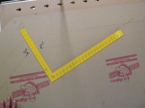
To lay out the angled joists (as well as the hips), I bisected the outside corners by placing a framing square on the line of the outside wall, set at a 5-in-12 pitch, which happens to be 67.5 degrees and is the correct setting to bisect a 45-degree corner. I extended the lines to the back of the bay with a long straightedge held against the blade of the square. Accuracy of these lines is critical because the centerlines for the angled framing ultimately determine the intersection point of the hips, upper ledger, and side nailers.
I drew a ledger that would span the entire width of the bay roof and attach to the brick wall. I also laid out the angled subfascia on the template. Normally there would be a common rafter right next to a hip rafter, but that would have given me three commons, so I drew in just two in conjunction with the ceiling joists below.
Ceiling first, then rafters
With conventional roof framing, the walls are built first, then rafters with birdsmouths land on the wall plates to form the eaves overhang. With my method, the ceiling joists extend beyond the walls as lookouts to create the eaves. The rafters then get a simple seat cut and land on top of the lookouts.
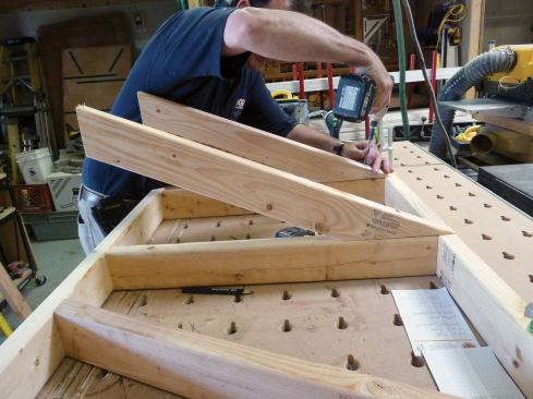
I took measurements for the parts of the ceiling assembly directly from the template, and then I assembled the parts on top of the template. Instead of nails, we used 3-inch construction-grade screws made by Grabber to fasten the framing together. Screws help to keep the pieces on their layout marks during assembly, and they also fasten the components more securely than nails, which is a plus for transporting and lifting the roof into position.
With the ceiling assembly clamped to the bench, I turned to the common rafters. With conventional roof framing, the run of a common rafter is measured from the center of the ridge to the outside edge of the wall plate. But the run of these so-called commons was the distance from the outside edge of the ledger to the outside edge of the subfascia. So I calculated their length with a Construction Master calculator. I entered the roof pitch and the run (measured off the template). I hit the “Diag” button. The resulting dimension was the length of the rafters measured from long point to long point. We cut the two common rafters and screwed them to the joists, taking care to keep the rafters perfectly aligned with the joists.
Next we measured between the centerlines of the two diagonal joists for the length of the “ridge,” which we cut and then screwed to the tops of the common rafters. On a typical hip roof, the ridge sits behind the ends of the perpendicular walls. But on this roof, the ledger is outboard of that position, so the member above— while functioning as a ridge for attaching the rafters—really is just an upper ledger for attaching the roof to the wall.


