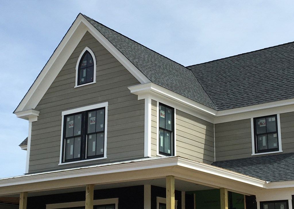
Cape May, N.J., has been a seaside resort since before the Victorian era, and the town has many homes in that period’s architectural style, along with examples of many other styles, as well. One feature that can be found in most of the older homes in this area is the crown-molding cornice. We see this detail on elaborate Victorians, traditional colonials, Greek revivals, and simple Capes.
Cornice is just a fancy word for the eaves detail at the edge of a building where the roof meets the walls, and on most houses, it includes the soffit and the fascia. With a crown-molding cornice, a decorative layer of crown molding is added to the fascia, and the roof extends to meet the upper corner of the crown. How to build one can be a point of contention for many builders who incorporate historical details on the new buildings they build.
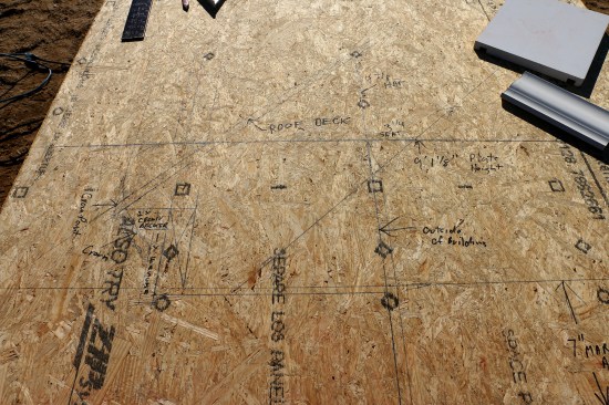
Creating a crown-molding cornice begins with a full-scale drawing of the details, including the wall-plate height and the frieze board above the windows.
Our crew is asked to include crown-molding cornices on just about every new home we build, and we’ve developed methods to create them using modern building materials and efficient building practices. Last fall, clients asked us to build a modern farmhouse on a five-acre lot in a nearby town. My father designed a traditional-looking home that fit in with the area’s architectural style and had a big front porch, tall windows, four steep gables, and traditional trim details—including crown-molding cornices.
Full-Scale Layout
I’ve built quite a few houses with this detail, with different roof pitches and different-size overhangs, and I like to draw out the detail before we begin the roof framing. Before cutting any rafters, I make a full-scale drawing of the eaves, including the roof pitch and all the molding details, on sheet stock. Using the drawing, a scrap of 1-by material to represent the fascia, and a scrap of crown molding, I can determine the rafter-tail layout, as well as the dimensions for the subfascia and the crown backer.
I always include the height of the top plate and the top of the window rough openings on the drawing. Many of the homes we build have a large frieze board that bridges the gap between the tops of the windows and the underside of the soffit, and I often adjust the birdsmouth of the rafter to create the desired dimension there; a shallower notch raises the rafter and allows for a larger frieze board.
For this house, because of the combination of a steep, 12:12-pitch roof and a window-header height of 91 inches above the finished floor, I needed to lay out a shallow birdsmouth to allow enough space for a 1×8 frieze board between the window heads and the soffit. While all these calculations could have been done mathematically, the full-scale drawing let me and the rest of the crew visualize the entire detail. Later, I also used the drawing to scale the gable frieze board and how the height relates to the return.
Once I determined the height of the soffit, which we would make out of 3/8-inch PVC material, I drew horizontal lines across the plywood to represent it. At 16 inches from the sheathing, I drew a vertical line that represented the outermost point of the crown molding. Then I worked backward from that line. The 4 5/8-inch PVC crown that I used for this job has a horizontal projection of 2 3/4 inches, so I drew another vertical line 2 3/4 inches toward the building to represent the outer face of the 1-by fascia. Another vertical line 3/4 inch toward the wall represented the back of the fascia and the front of the subfascia. I made a final vertical line 1 1/2 inches toward the wall for the full width of the subfascia.
I chose 2x6s for the subfascia material on this project, so I measured up 5 1/2 inches from the top of the soffit to show the whole subfascia. I always draw an “X” from point to point on any 2-by material, so that I don’t get confused with what lines indicate solid material. Next, I set the bottom edge of the 1-by scrap 1/2 inch below the soffit and marked the actual fascia location on the drawing.
From the top of the subfascia in my drawing, I extended a horizontal line toward the 16-inch overhang mark. The intersecting point between the two lines was the long point of the rafter for the horizontal cut that housed the crown and fascia detail. From that point, I drew a line representing the roof pitch as far up the layout sheet as I could. Parallel to the roof-pitch line, I drew two more lines, the first 9 1/4 inches lower to represent the bottom edge of the rafter and the other 1/2 inch higher to show the thickness of the roof sheathing. Where the bottom edge of the rafter crossed the wall layout gave me the layout for the birdsmouth on the rafters.
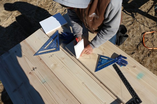
The drawing also shows the rafter-tail cuts along with the placement of the subfascia and crown backer. While transferring the layout to the pattern rafter, the crew double-checks the details.
I use the line for the top of the roof sheathing to set the height of the crown molding, which depends on what roofing material is used. This house would have a heavy-duty asphalt roof, so I held the top of crown to the middle of the sheathing with the bottom against the fascia. (For roofs with cedar shingles, I hold the crown a little higher to compensate for the cedar breather. We use drip edge on our roofs, but I don’t want it to conceal too much of the crown.)
When I was happy with the height of the crown, I traced the front and back edges. The line from tracing the back of the crown also formed the beveled edge of the 2-by nailer or backer strip behind the crown. That nailer butted up to the subfascia on one side and to the level rafter cut on the other.
Cutting the Rafters
With the drawing complete, I turned to the rafters. I transferred all the pertinent parts of the drawing to the pattern rafter tail, including the birdsmouth and the cuts for the overhang. I also transferred all the fascia details along with the crown and the beveled-nailer layout to double-check them before cutting the first pattern rafter. With all the details for the overhang on the rafter tail, I determined the common-rafter lengths in the usual way.
There were three cuts on the rafter tail: a level cut at the bottom of the subfascia, a plumb cut at the back of the subfascia, and a level cut at the top of the subfascia to give the rafters their long point.
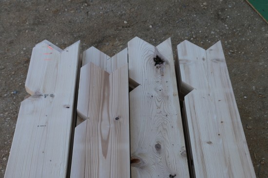
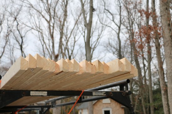
Then they use the pattern to cut the rafters before stacking them.
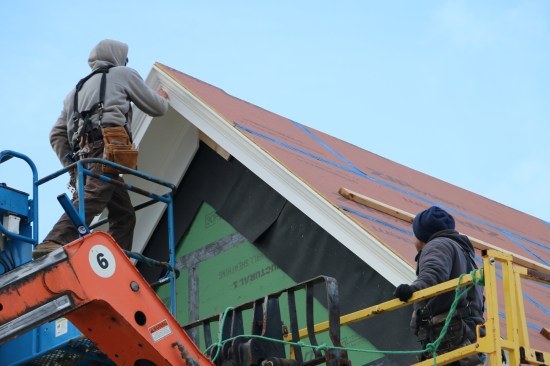
Using the pattern rafter, we cut all the common rafters for the house, while the rest of the crew worked on another part of the project. When cutting rafters, I like to make two stacks with their tails opposing. That way, we can use a telehandler to lift the rafters up to the crew members on the roof, and they don’t have to spin the rafters around before installing them. For this project, we also made additional stacks of rafters without tail cuts, to be used in areas where the roofs intersected.
The other framing component we needed to prepare was the crown backer, which we made from 2-by material with a 38-degree beveled rip. We pulled the backer dimensions from our drawing by measuring from the face of the subfascia to the point of the rafter tail. I typically make the backer a little shy of this dimension so that the crown can be adjusted or shimmed for any irregularities in the framing.
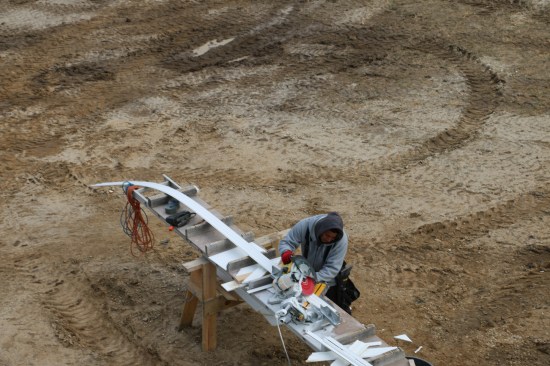
The crew mills the crown backer in a shop and transports it to the site.
For the 4 5/8-inch crown molding that we used here, the crown backer worked out to be about 3 1/8 inches to the long point. Because of the large amount of heavy ripping that was required to make all the backer for this large custom home, it was easier and faster to rip the stock in my shop using a heavy-duty shop table saw, and then transport the pieces to the site.
Building the Cornice
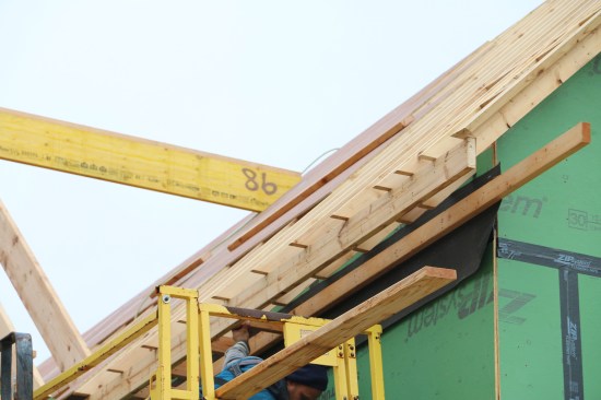
The following day, the crew installed the bulk of the common rafters and ridges. The 2×6 subfascia, which fit into the notch cut in the rafter tails, came next. At the same time we installed the subfascia and crown backer, we also installed the framing for the soffit. For this rigid soffit with a vent strip, the framing consisted of a ledger on the wall and 2-by blocking between the subfascia and ledger that sat next to each rafter. We installed a 12-inch rip of 30-lb. felt paper behind the soffit ledger to tie into the rest of the building paper that would be installed with the siding.
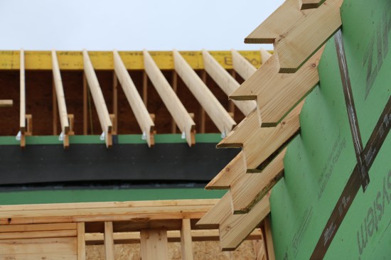
The crew installs all the common rafters before beginning to frame the cornice.
The subfascia fits into the notch cut into the rafters, and the soffit ledger attaches to the wall over a layer of 30-lb. felt paper.
The crown backer fit into the corner created by the subfascia and the horizontal rafter cut. For inside and outside corners, we joined the lengths of backer with miters to provide maximum nailing for the crown. Once we’d finished a few sections of the eaves framing, a couple of crew members began sheathing the roof. When the roof sheathing was done, we turned to finishing the eaves on the level sections, including the gable-end returns.
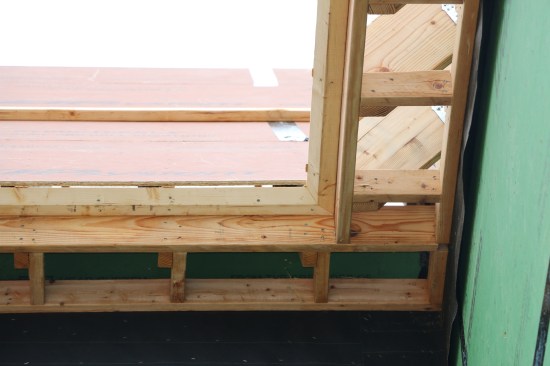
Blocking next to each rafter spans between the subfascia and the ledger. The angled crown backer fits against the subfascia and the horizontal cut of the rafters. The backer is mitered at all inside and outside corners.
The 3/8-inch PVC soffit material came in large, 4×18-foot sheets that we ripped to the desired widths. The level soffit consisted of two 5-inch-wide rips with a 2-inch-wide plastic strip vent in the center. We installed the outer rip of soffit first, keeping it 1/4 inch out from the subfascia. Then came the vent strip and the inner PVC strip.
Rips of 3/8-inch-thick PVC flank the plastic vent strip for the soffit finish on the level eaves. The outer edge of the soffit overhangs the subfascia by 1/4 inch.
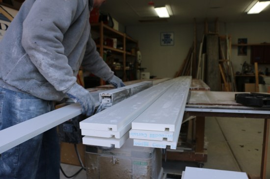
The crew prepares fascia stock by first ripping 1x10s to the proper widths in the shop. They cut a dado 1/2 inch from what will be the bottom of the fascia.
The 1-by fascia for the eaves detail needed to be approximately 4 1/2 inches tall. To reduce waste, I bought 1×10 PVC stock and then ripped it to width. We also cut a 1/2-inch-wide-by-3/8-inch-deep dado in the material to accept the overhanging edge of the soffit material while leaving 1/2 inch of the fascia below the soffit. We’ve found that this method produces a cleaner detail and reduces errors, while creating a consistent fascia reveal along the soffit.
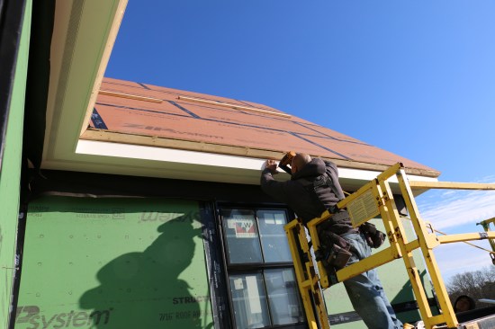
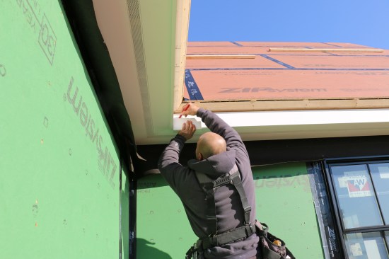
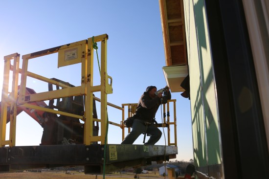
The crew nails the fascia in place. The dado creates a consistent reveal and shadow line along the edge of the cornice.
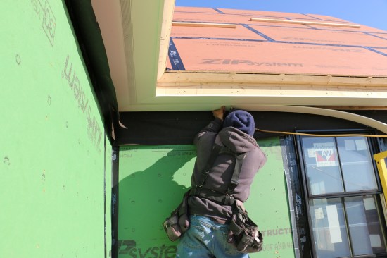
Using a gauging block to draw a line for the bottom of the crown molding ensures its accurate placement.
Because the PVC crown stock is so floppy, the crew cuts it on the flat, using the detents on a chop saw.
After we nailed on the fascia, the crown completed the detail. Working off the bottom edge of the fascia with a gauge block, we marked the lower line of the crown to keep the amount of exposed fascia consistent throughout the house. The PVC crown stock is floppy, so we cut all the crown miters for the level eaves with the material flat on the saw table and the saw angles at the preset detents. Long extension tables for the chop saw were a big help here. We nailed the crown to the fascia at the gauge-block lines first, and then nailed the rest of it to the backer, using the gauge block to make sure the crown stayed in line.
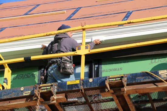
The crew then aligns the crown with the gauge lines and nails the pieces into place.
The gauge block is used again, this time to ensure that the fascia reveal is even all the way around the house.
Where the eaves were longer than our stock, we joined the PVC pieces with 30-degree scarf joints and Christy’s Red Hot White Vinyl Adhesive. We did not glue the soffit-to-fascia joint, leaving material free to expand and contract independently within the dado joint.
Returns and Gable
At the lower ends of the gables, we extended the soffit framing and built boxes out of the subfascia material to frame the returns. After applying a layer of 30-lb. felt behind the return, we nailed the box to the gable wall and to the eaves framing for a secure attachment. The crown backer then continued from the eaves, wrapping around the return. We sheathed each return with a cover that was pitched away from the gable wall.
We trimmed the gable returns the same way as the rest of the eaves, except that we used a solid piece of 3/8-inch PVC for the soffit instead of the vented strips. The soffit material overhung the framing on the three exposed sides to engage the fascia. Then the fascia and crown wrapped around the return.
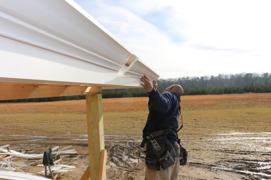
The fascia and crown then wrap back to the gable wall.
When we’d finished trimming the returns, our metalsmith came in, templated the tops of the returns, and made stainless steel caps for them. These caps have a drip edge that turns down over the two exposed sides. At the wall, the cap turns up and is bent to the underside of the roof deck to shed water away from the building.
When we framed the gables, we sized the barge rafters and attached the crown backer so that the fascia detail would match the eaves. As with the level eaves, we installed the soffit material on the gable overhangs first, using solid material instead of vented strips. As with the rest of the cornice, the fascia installed with the dado slipping over the overhanging soffit material. We installed the crown on the gables the same way, gauging off the edge of the fascia. At the peak where the two lengths of crown met, the continuous backer allowed us to shim and tweak the joint until it was perfect. I’m no math whiz, so this was the only place that we cut the crown placed at an angle in the chop saw.
The entire cornice return will be capped with stainless steel. The cornice detail continues up the rakes, and the crown pieces meet at the peak with a perfect miter.
At the bottom of the gable eaves, we kept the trim pretty tight to the return caps, with just enough space to allow the area to dry out. Large gaps in these areas can encourage wasps and other pests to take up residence. While we were still set up on the gable, we installed the gable frieze boards, spaced off the wall for the siding to slip behind, and the house was finally ready for the roofers.


