My company recently built a large, high-end house with a modern design on a North Carolina reservoir. One of the most prominent features of this home was a wide overhang whose projections varied from just under 3 feet to more than 7 feet in some sections (around 4 feet was the typical overhang for most sections of the multiplane roof).
As a design element, the wide overhang provided ample shade and helped keep rainwater away from the structure, but it presented two challenges. First, to manage roof runoff, the owner (a successful concrete contractor who is very aware of water and site drainage issues) wanted gutters to collect the runoff from the vast and complex roof and deposit it far from the home’s foundation. With wide overhangs, however, conventional downspouts on the exterior of the house were out of the question.
Second, in the wind zone for this North Carolina site, wide overhangs present an extreme uplift condition. To overcome these intense forces, the engineer specified some substantial structural elements to strengthen the roof. By cleverly integrating a unique system of concealed gutters with these structural roof elements, our team was able to successfully manage both challenges.
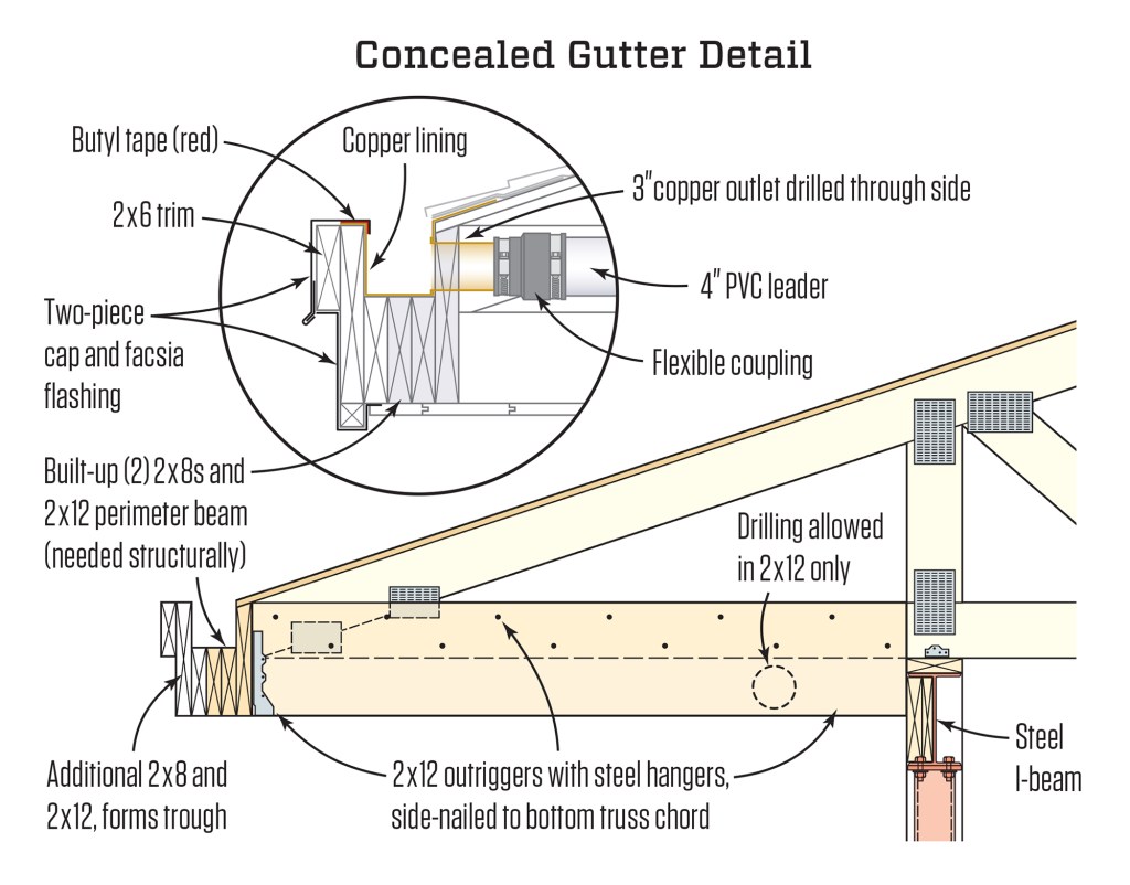
The engineer required three 2-bys for a perimeter beam.
The outer members complete the gutter channel.
Structural Elements
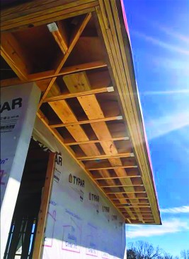
We framed the roof with trusses, but in order to handle the reaction forces at the fascia end of these trusses, the engineer specified a perimeter beam to tie the ends of the trusses together. We built up this structural component from a 2×12 and two 2x8s sandwiched together. This perimeter structure was secured to 2×12 outriggers with steel hangers and side-nailed to the overhang portion of each truss. The outriggers braced the perimeter beam back to a continuous steel I-beam that tied the tops of the exterior walls together (see illustration, below).

Tim Healey
Drainage Components
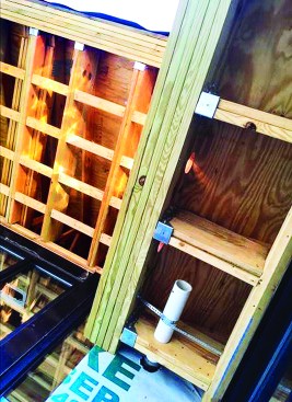
To form the gutter trough, we added another 2×8, followed by two 2x12s, to the perimeter beam. While these framing members were not strictly needed for the structure, they didn’t hurt and they provided an easy means to create a channel that we could line with copper to create an integral gutter around the perimeter. In a few cases, the channel beams were placed high enough on the roof that we could drill drainage outlets in the bottom of the channel. But in most cases, we had to drill through the side. The engineer allowed us to drill through the beam, but we had to limit the hole diameter to 3 inches.
Multiple 3-inch drainage outlets Y together and step up to 4-inch runs through the soffit area.
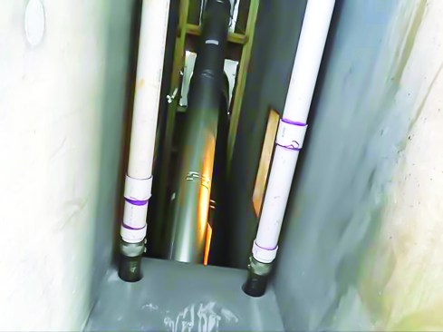
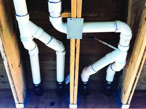
Vertical drains were routed through several concrete chimneys. Note the rubber sleeves connecting the PVC to the copper outlets at the gutter, and the transition to cast iron where drains run near living space
To handle the sheer volume of water we expected from seasonal Carolina storms, we ganged multiple outlets, and enlarged to 4-inch pipe inside the eaves structure to reduce the number of leaders. To accommodate differential movement between the copper outlets and the PVC drains, we connected our drains to the gutter using rubber sleeves.
The PVC drains ran through the soffit area, turning to run parallel to the exterior walls. The engineer allowed us to drill through the 2×12 outriggers, as well, but not through the truss chords. While we didn’t have a lot of room, we were able to pitch the drainage pipes to achieve the required 1/8 per foot (1%) slope needed for 3- and 4-inch pipe.
To drain out of the eaves area, we ran the PVC to numerous chimneys placed along the exterior walls. We core-drilled through the formed concrete chimneys to run our verticals inside to the foundation level. In areas where the vertical drains ran near living space, we transitioned to cast iron to limit noise. We then transitioned back to PVC below floor level where the drains joined to exit alongside the foundation perimeter drains to daylight, far from the house.

Long runs for the copper liner were bent off site.
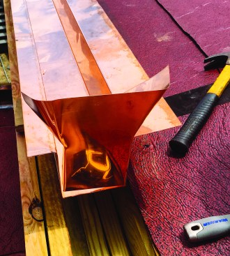
End caps, corners, and outlets were fabricated on site.
Finish Details
We pre-bent the long copper troughs off site and site-bent the end caps and outlets, mechanically joining the copper with rivets before soldering watertight seams. All this work was done after the roof had been dried in, so after installing the copper liner, we taped along the edge of the copper as a temporary measure until the roofing could be installed.
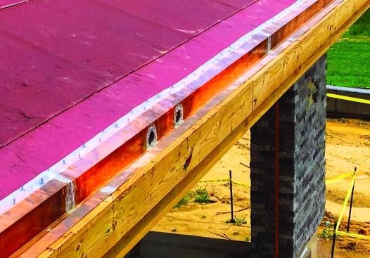
They were secured with both rivets and solder.
To finish off the fascia, we installed a two-piece aluminum fascia cap. The first piece nailed to the outer 2×12, and was counter-flashed by a second piece that locks in with cleats, so there were no visible fasteners from the ground. This second piece overlaps the copper liner but is separated with butyl tape so the two metals do not have a chance to galvanically react.
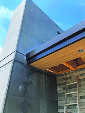
The roof was dried-in early; the tape was temporary until the roof could be installed. A two-piece fascia cap and T&G soffits finish off the installation. The entire gutter system is completely concealed.
Once the project had been completed, you wouldn’t know there were any gutters and downspouts on this roof. Yet this summer, a number of torrential thunderstorms have already passed through, and the system handily carried all the runoff away with no detectable spillover.
Photos by Grainda Builders


