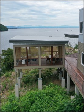
In the summer of 2017, the company I work for, Hayward Design Build, broke ground on a new high-performance home on the shore of Lake Champlain in northern Vermont. The 2.5-acre, mostly wooded site was located on the tip of a small peninsula and featured a rock outcropping that dropped off steeply to the water’s edge some 70 feet below. The homeowners wanted their new home to blend into the landscape while also taking advantage of the property’s stunning 230-degree lake views. With the help of architect David Pill of Pill-Maharam Architects in Shelburne, Vt., they designed a sleek minimalist-style structure and sited it on the point’s rocky bluff.
Because of the sloping ledge, the home’s foundations needed to be a mix of slab-on-grade and pier construction. The living areas in the main part of the home would be supported by a slab-on-grade, while the bedroom-office wing (which doglegged 45 degrees from the main structure) would be “floated” on concrete piers. An important part of the design was a wrap-around deck running the full length of the home’s southern elevation and along portions of the east and west elevations, which would also be built on piers (see “Hybrid Foundation” plan, Figure 1). Although the home’s aesthetic was simple, building the complicated, near Passive House–level structure and expansive deck areas proved otherwise.
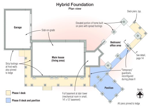
Figure 1. Built on a rocky bluff, the home’s foundation was a mix of slab-on-grade and pier construction. A wrap-around deck and screened porch (or “pavilion”) were also supported by piers. The project’s two phases spanned three years.
Pinning to Ledge
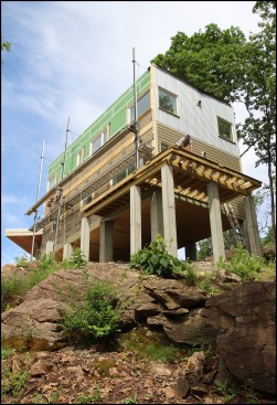
During the project’s design phase, a geotechnical engineer inspected the geology of the proposed house placement and adjacent areas and consulted with the structural engineer. They concluded the rock outcrop was ledge (as opposed to large, fragmented boulders), but that it was fractured and could become unstable if it were site-blasted to make way for full-depth foundations. This brittleness of the bedrock necessitated the “half slab-on-grade, half pier” foundation solution (Figure 2).
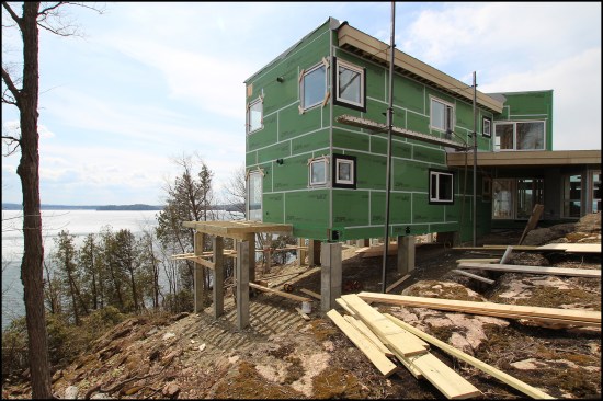
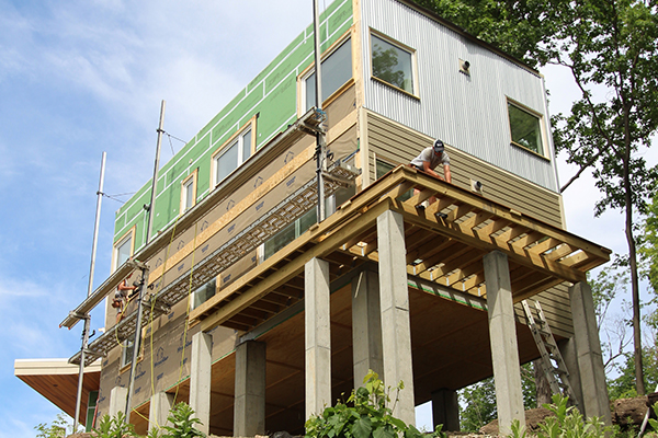
Figure 2a. The bedroom-office wing was “floated” on the piers. Here, the deck was being framed on the home’s elevated southeast corner.
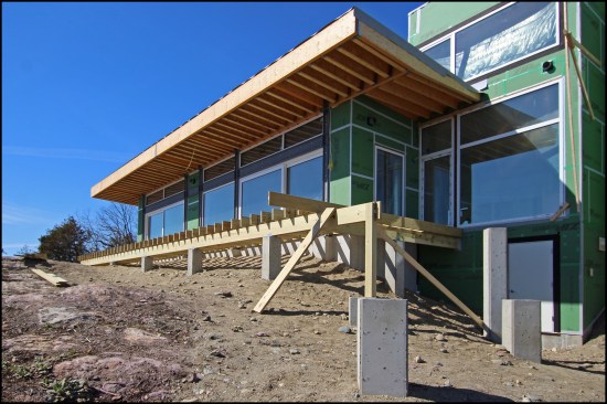
Figure 2b. The larger deck off the main living area (where the slab on grade was installed) was close to grade and supported by shorter piers.
In lieu of blasting, we brought in an excavator with a hydraulic breaker hammer to chip out ledge for the footings. The excavator carved trenching for strip footings out of the rock where frost walls were needed in the slab-on-grade areas, and hammered out holes for individual footings at pier locations in the bedroom wing and deck areas. Larger holes were made for spread footings at piers supporting the “floating” house.
Dowels. To pin the footings to ledge, L-shaped dowels were embedded 12 to 18 inches—depending on the footing size—into the rock and set with Hilti HY200 adhesive. After drilling the holes, we blew them clean with compressed air and then set the dowels. At the frost walls, we pinned the strip footings to rock with rebar dowels in a staggered pattern and installed dowels at each of the large spread footings and smaller deck footings. The size and number of dowels varied depended on the footing size.
Working concurrently on the slab-on-grade and piers, the foundation crew poured the footings and frost walls, then assembled the heavy rebar reinforcement for the piers. To level the irregular rock surface for the slab-on-grade portion of the home’s foundation system (a 4-inch radiant slab in the home’s conditioned space with 8 inches of sub-slab EPS insulation), we trucked in gravel and fully compacted it.
Piers. The larger, 18-inch-square house piers were heavily reinforced with continuous #6 vertical rebar, while the 12-inch-square deck piers were reinforced with continuous #5 rebar. Depending on the sloping topography, the height of the piers ranged anywhere from 2 to 14 1/2 feet (see “Connection Details” illustration, Figure 3).
After the piers were poured, the site was backfilled with engineered soils.
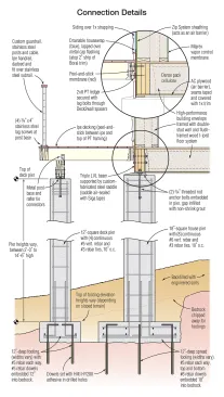
Figure 3. Taken through the bedroom wing, the section drawing shows the footings for the heavily reinforced piers pinned to the ledge with L-shaped dowels. Dowel size, number, and depth varied depending on footing size.
Prepping for a Pavilion
Included in the foundation work was the installation of eight piers for a stand-alone, screened-in porch (or “pavilion”) located in the middle of the home’s south elevation. The pavilion was in the initial job scope, but due to budgetary issues, it was deferred to a future Phase II. As a result, the middle portion of the wrap-around deck was left unbuilt for a year and a half while the homeowners contemplated whether to build it. In the interim, the deck section adjacent to the bedroom wing and the one at the main house were treated as two separate decks, with code-approved guardrails. [Note: The pavilion and middle deck section were completed this summer. Click here to see completed project—“A Pavilion Perched High on a Ledge”].
Framing Decks, High and Low
We began installing the deck at the higher, southeast corner of the home, where the bedroom wing’s elevated first-floor 14-inch-deep wood I-joists were flush-framed to triple LVL rim beams (Figure 2a). The built-up LVLs ran around the perimeter of the floor system and were connected to the piers with custom-fabricated steel saddle connectors (see “Connection Details,” Figure 3). These LVL rim beams provided plenty of “meat” for the threads of the lag bolts we used to secure the deck ledgers.
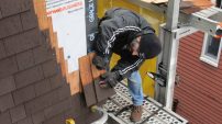
Prior to installing the 2×8 PT ledgers, we installed Fentrim 430 Grey flashing tape (sigatapes.com), starting a couple of inches above the ledger and running to the bottom of the wall. Fentrim is a semi-permeable flashing tape that offers effective protection from air leakage and water penetration. I’ve found that the peel-and-stick tape hugs the shafts of the fasteners well during installation.
Deck connections. We secured the 2×8 PT ledgers for the narrow decks in the elevated southeast corner with lag bolts driven through 1/2-inch-thick polypropylene Deck2wall spacers (deck2wallspacer.com). These spacers stand the ledger off the framed wall to protect it long-term from water and debris (Figure 4).
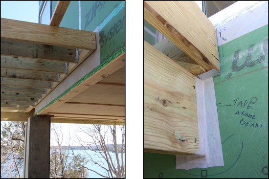
Figure 4. Ledgers were lag-bolted through spacers to the elevated floor’s triple LVL rim beams spanning the piers (left). Fentrim flashing tape was used for both water- and air-sealing. Here, it air-seals a deck beam pocketed into a wall (right).
At the outer deck, a triple PT 2×10 beam spans between the deck piers. We connected the built-up beams to the piers with metal post-base anchors with 1-inch standoffs to help prevent rotting. 2×8 PT joists cantilever over the carrying beams and attach to the beam with rafter tie connectors. At the ledger, the joists are flush-framed and attached with joist hangers.
Down low. We framed the wider grade-level deck along the south and west elevations similarly, though it required beefier 2×10 joists with a triple 2×12 carrying beam for the longer spans. At the top of the frost walls, we attached the deck ledger to the concrete with 1/2-inch threaded rods set with Hilti HY200 adhesive, again using Deck2wall spacers to stand the ledger off the frost wall (Figure 5).
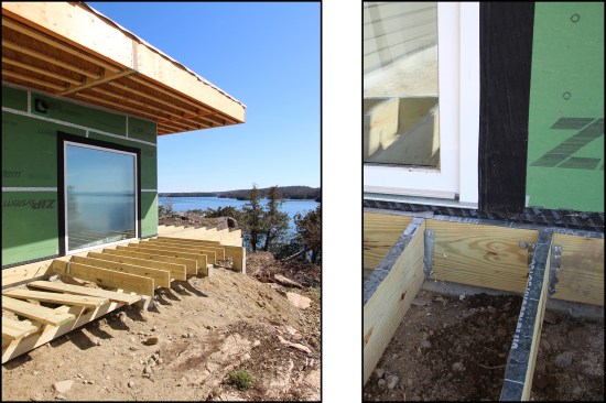
Figure 5. In the slab-on-grade areas, the wider grade-level deck section was framed with beefier 2-by stock (left). Threaded rod set in adhesive attached the ledgers to the top of the frost walls (right). Peel-and-stick capped the 2-by stock.