
More than a few of my jobs have been for clients who contacted me after reading one of my JLC articles. That was the case for this project, which involved replacing four structural support columns in the basement of a three-story house built in 1895. My client, who had just purchased the house, was concerned about cracks in the basement’s concrete slab floor that were radiating out from each column, as well as about some dips in the flooring at the first-floor level and a few binding pocket doors. The scope of work included additional columns as needed to address these issues.
Other contractors had looked at the job but declined to take it on; I’d done similar work before (see “Shoring a Sagging Floor,” Mar/12), so I knew what to expect. Still, this was one of my most challenging basement projects, with a concrete floor consisting of two slabs poured at separate times, one on top of the other, over a subbase of broken-up ledge. The bases of the four steel columns were bearing on the stone substrate and buried beneath the two slabs, so the concrete needed to be broken up just to remove the embedded columns.
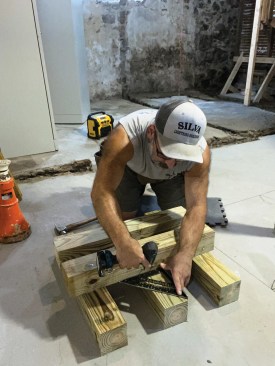
To provide a solid base for his screw jacks, the author assembles cribbing from 4×4 posts.
He shims the cribbing level either with composite shims (where the gap is less than 1/2 inch) or with sawn stock.
I started by assembling cribbing from 8-foot-long 4×4 pressure-treated posts cut into 2-foot sections. Solid support is needed for the 20-ton screw jacks that I use to lift floor framing enough to remove a support post, and because basement slab floors are rarely level or smooth, I always shim the assembled cribbing carefully. Then, while jacking up the temporary 4×4 supports, I check them frequently for plumb in both directions. The cribbing at each location would be in place for about a week, during which time a lot of weight would bear on the assembly. With plumbing, waste lines, and gas supplies at stake, a major shift in the position of the building could be catastrophic, so I worked slowly and carefully to make sure everything was solid, flat, level, and plumb as I proceeded.
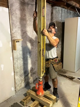
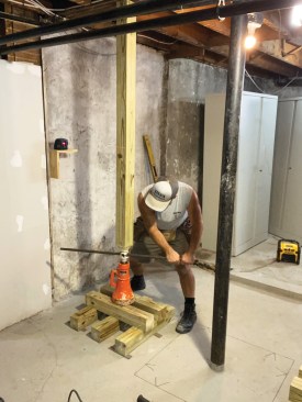
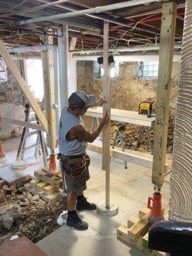
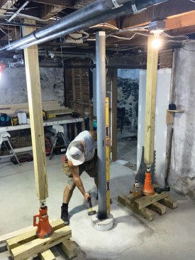
The author adjusts the support post until it is perfectly plumb in both directions, then turns the screw jack slowly to raise the floor framing just enough to take pressure off the existing column (no more than 1/4 inch).
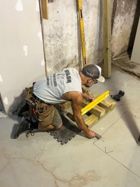
The author sets a laser level on a shelf mounted to the basement wall to mark reference lines on the temporary support posts, which can be periodically checked to make sure that they haven't shifted while working on the column.
I space a pair of temporary supports about 4 feet apart when I’m removing a column and typically jack up existing framing no more than 1/4 inch—just enough to take the weight off the column. To make sure that the temporary supports don’t shift positions relative to each other, I set up a laser level in a convenient location, mark a reference elevation on each support post, and check the marks periodically.
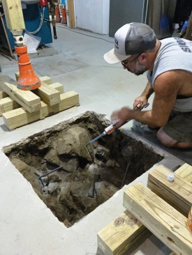
After breaking away enough of the slab with a rotary hammer to remove the old column, I enlarged the opening in the slab to 30 inches square. Then the hard part began: removing enough of the underlying soil and broken ledge to provide solid bearing for a new concrete footing. In some cases, the rocks were large enough and extended far enough underneath the slab that attempting to remove them would have caused the edge of the slab to collapse. So, for each of the nine new footings that were needed to replace the four original ones, I had to make a careful judgment about what material could be removed and what could remain.
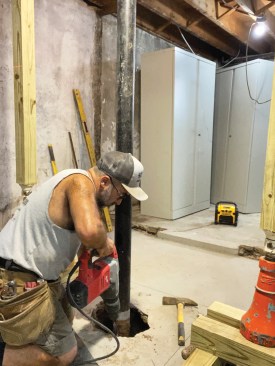
Because the bases of the existing columns were buried under the basement slab, the author had to chip away the concrete with a rotary hammer prior to removal of a column.
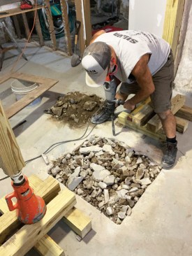
With the column out of the way, the author then enlarged the opening in the slab for the new footings. Here the broken ledge underneath the slab is clearly visible.
I loosened rocks and dirt with a small shovel and grub hoe, then switched to a flat bar and my hands to remove as much as I could from each hole. But the key to clearing the holes was a wet/dry vac fitted with a 2-inch-diameter hose, which quickly sucked up loose dirt and small stones as long as the soil wasn’t too damp.
Normally, I reinforce footings with a grid of #4 rebar, but for eight out of the nine new footings, I instead drilled a series of 5/8-inch-diameter holes at least 4 inches deep into the larger rocks. Then I squirted epoxy adhesive into the holes and filled them with 8-inch lengths of rebar to tie the new concrete footings to the subbase.
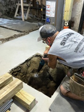
After removing as much loose material as possible to provide solid bearing for the new footing, the author drilled holes in the large rocks remaining embedded beneath the slab for rebar dowels.
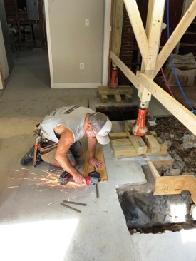
The author used an angle grinder to cut the 1/2-inch rebar dowels into the short lengths needed to fit into the 5/8-inch diameter holes drilled in the rocks.
Before inserting the rebar dowels, the author injected epoxy adhesive into the holes.
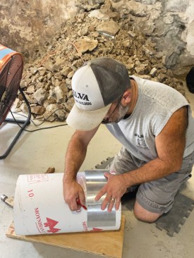
The author cut 10-inch diameter tube footing forms into 6-inch lengths.
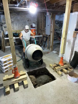
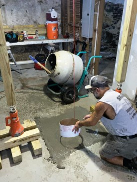
It took about fifteen 80-lb. bags of concrete to pour each 30-inch square by 12-inch deep footing, which the author mixed up one bag at a time.
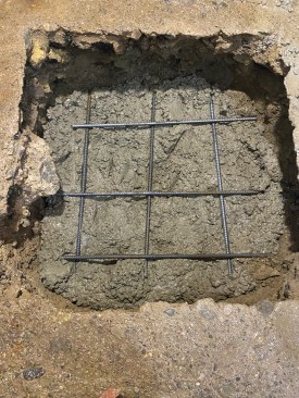
Only one of the footing holes was rock-free; here, the author reinforced the concrete footing with a rebar grid placed about a third of the depth of the hole.
To raise the base of each new column above the level of the existing slab, I used short lengths of 10-inch-diameter tube footing forms to create monolithic footings and piers. I used a length of aluminum flashing to mark the cut line for each 6-inch-long section, then slowly scored my mark with a sharp utility knife so that the tops of the cardboard forms would have a clean edge, making it easier to screed the tops of the piers smooth.
For each 30-inch-square-by-12-inch-deep footing, I had estimated about 15 80-pound bags of concrete (though I used less because of the irregular stone remaining in most of the holes), which I mixed up one bag at a time. After filling a hole, tamping it with a shovel to remove air bubbles, and screeding the new concrete flush with the old slab, I embedded a 6-inch-long footing form about 3 inches into the wet concrete to create a raised pier. To make sure the piers were centered underneath the column locations, I hung a washer tied to a string from a screw driven into the framing. I filled the form with concrete, then inserted additional short lengths of rebar into the pier before leveling it and screeding the top smooth.
After screeding the wet concrete flush with the existing slab, the author inserted one of the cardboard tube footing forms into the concrete.
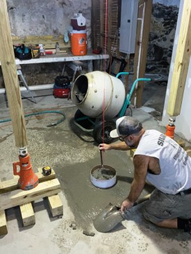
A weighted string fastened to the column location marked on the beam above allowed the author to properly center the form in the footing.
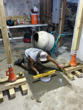
After embedding the form three inches deep into the concrete, the author filled it with more concrete, inserted short lengths of rebar, leveled the form, and screeded and troweled the top of the pier smooth.
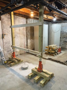
The author screwed a pair of 2×4 braces to the support posts to stabilize them while the concrete cured to full strength. The author typically waits about a week before placing a load on new concrete.
I typically wait about a week for new concrete to cure before placing any weight on it. In the meantime, I screwed a couple of braces to the temporary support posts and moved on to the next column location on this project.
To find a precise measurement for the length of the new columns, I used a couple of shorter lengths of 2×4 to make an adjustable story pole, positioned the column base on the footing, and screwed the Springfield plate column cap to the beam. By resting the bottom of one 2×4 on the dimpled plate column base, pushing the other 2×4 up tight against the column cap, and marking a reference line across both 2x4s, I could then transfer the exact length to the column.
The author made a simple story pole out of two short lengths of 2x4s to get a precise measurement of the distance between the top of the footing and the bottom of the floor framing.
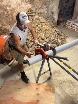
To make cutting the Lally column to length easier, the author holds it in place with a large aluminum pipe wrench to keep it from spinning while turning the cutter.
One column down, only eight more to go.
On this project, I installed 4-inch-diameter Lally columns (which are considerably stronger than typical 3 1/2-inch-diameter columns), using a large aluminum pipe wrench to hold them in place while I cut them to length. I ended up installing nine new columns: four to replace the original ones and the rest to provide additional support for the floor framing.
Photos by the author.


