Our company, which specializes in structural repairs, was recently called to an expensive residence outside of Chicago. A number of contractors had been to this house to bid on replacing a large wrap-around deck, but they had concerns; extensive rot of the ledger board signaled deeper structural problems that exceeded their expertise. Our inspection revealed numerous places where poor flashing had led to extensive water intrusion problems. The worst was at the base of large banks of windows on the A-frame-style wing that the deck wrapped around. Water running off the large expanses of glass had leaked for years through the base of the window walls, jeopardizing not just the deck ledger but the entire floor-system supports, which served to tie together the A-frame rafters. The house was on a hill and exposed, resulting in significant lateral wind loads on the steep roof, so a rotting floor system put this entire A-frame at risk of collapse.
Preparing to Rework the Load Path
1
of 8
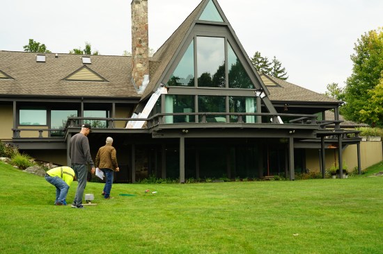
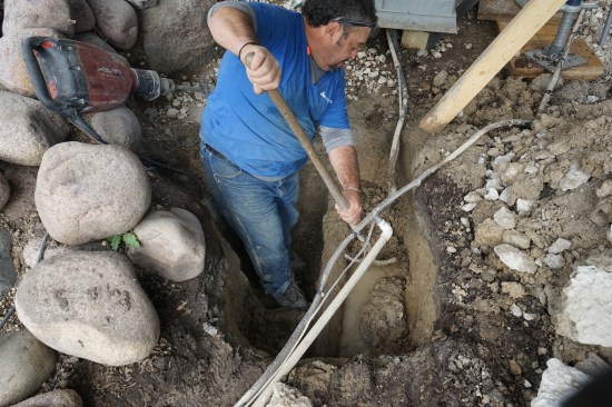
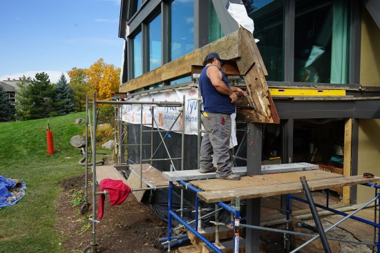
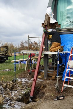
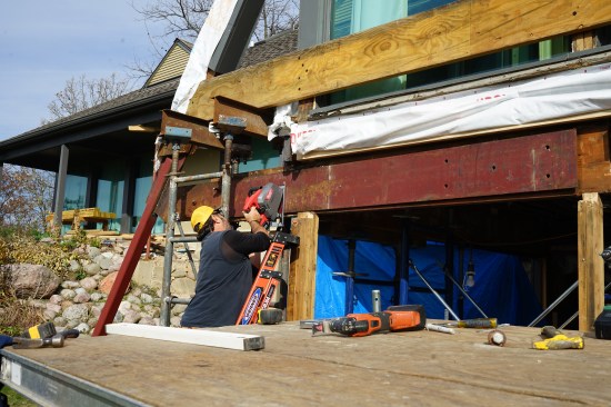
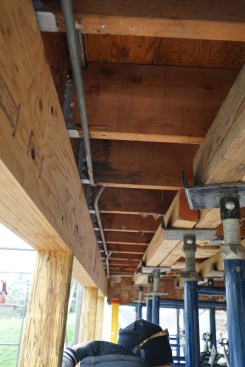
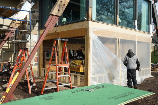
This photo shows the deck wrapping the A-frame-style wing of the…
This photo shows the deck wrapping the A-frame-style wing of the house during the initial investigation by the author’s company.
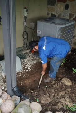
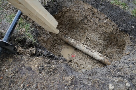
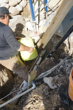
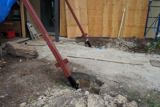
Excavation in preparation for drilling helical piers was done by…
Excavation in preparation for drilling helical piers was done by hand to carefully work around utilities.
A lumber extension attached to a rafter revealed that a waste li…
A lumber extension attached to a rafter revealed that a waste line was in the exact location where a pier needed to be drilled.
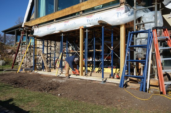
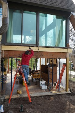
After protecting the floor below the A-frame wing, subcontractor…
After protecting the floor below the A-frame wing, subcontractors from the window company removed the lower windows.
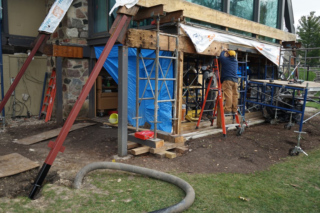
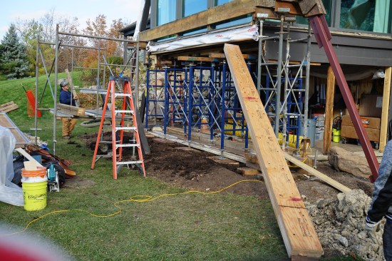
Shoring was erected to support the floor during demolition.
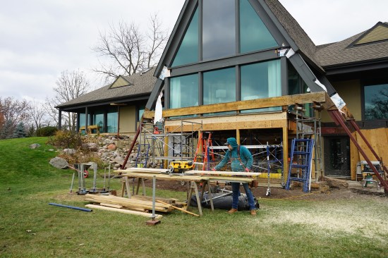
To complete demolition of the old deck, additional shoring was e…
To complete demolition of the old deck, additional shoring was erected to the left and right of the A-frame gable end. This shoring supported the roof extending over the deck on each side.
The original structure appeared to be built with clad, heavy timber rafters that continued past the roof overhang and tied into a clad, horizontal timber beam, which completed a triangle. After we removed the cladding from the rafters, though, we discovered they were constructed from two roughly 3-by-14-inch boards sandwiching a 1/2-inch steel flitch plate welded to a flitch plate in the horizontal member. The floor system sat above this horizontal beam. This design may have worked while the wood framing was sound, but once the wood rotted out, the integrity of the bolted assembly was severely compromised. Rather than try to reproduce this triangular load path, we worked with our engineer on a repair that redefined the load path: By driving helical piers at the same angle as the slope of the roof, the thrust of the rafters would be supported in-line with the rafters. We also supported the floor system with laminated veneer lumber (LVL) beams and completely reframed the supporting walls to create a robust structure with redundant support paths.
Installing Diagonal Piers and Columns
1
of 13
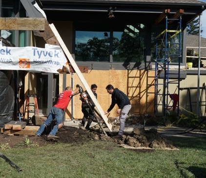
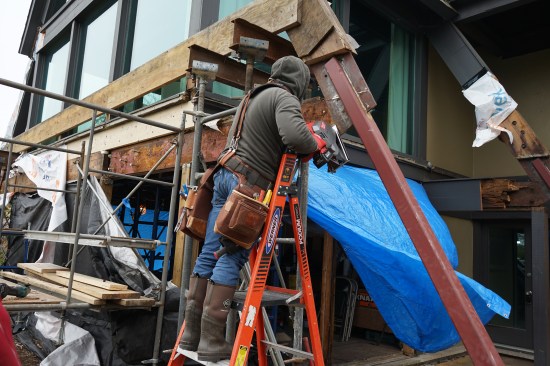
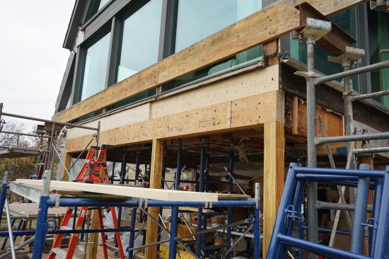
The crew has installed a temporary LVL beam across the face of t…
The crew has installed a temporary LVL beam across the face of the gable end to prevent the roof from spreading. Toby Bonilla of Great Lake Builders begins to strip the rotted end of the rafter to expose a flitch beam that tied the A-frame-style gable together.
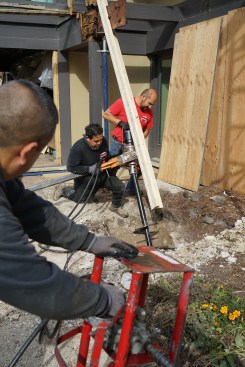
The installers drove the piers parallel to rafter extensions on …
The installers drove the piers parallel to rafter extensions on the A-frame gable. A total of four helical piers were drilled, two on each side of the A-frame gable.
Two-by lumber extensions (nailed in an “L” shape to keep the…
Two-by lumber extensions (nailed in an “L” shape to keep them straight and stiff) projected the line of the rafters to guide the installation of the helical piers, which were drilled at the same angle as the pitch of the roof.
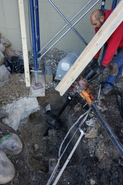
Hydraulic pressure is monitored by a gauge mounted between the h…
Hydraulic pressure is monitored by a gauge mounted between the hydraulic pump and the drive cylinder. Each pier is driven until the gauge shows the force (in lbs) of resistance equal to the reaction weight specified by the engineer.
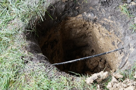
Here is the pier that landed exactly where a waste drain pipe ra…
Here is the pier that landed exactly where a waste drain pipe ran, so a section of that pipe was removed.
Once the pier was driven, a section of the waste line was replac…
Once the pier was driven, a section of the waste line was replaced. Backfilling was done by hand to avoid dislodging the repaired pipe section.
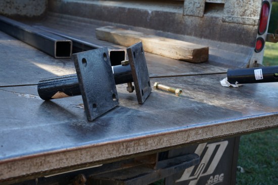
These end caps were fabricated for the ends of the helical piers…
These end caps were fabricated for the ends of the helical piers. The author’s crew was then able to connect steel columns that spliced onto the existing flitch plates at the rafter ends.
After each pier had been firmly driven into place, Jorge Garcia …
After each pier had been firmly driven into place, Jorge Garcia of Garcia Welding based in Lake Villa, Ill. field-welded an end cap to the top of each helical pier.
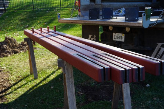
The four high-strength-steel (HSS) diagonal columns were fabrica…
The four high-strength-steel (HSS) diagonal columns were fabricated with slots at one end of the columns. These slots will slip over the existing flitchplates on the house.
A strong field weld requires clean surfaces free from rust and p…
A strong field weld requires clean surfaces free from rust and paint. Prior to installing the columns, a worker used a grinder to clean the surface of the existing flitch plates.
The bottom end of the diagonal column has been cut to length and…
The bottom end of the diagonal column has been cut to length and welded to the end cap on the pier.
Jorge Garcia welded the columns to the flitch steel at the end o…
Jorge Garcia welded the columns to the flitch steel at the end of a rafter.
After the diagonal columns were firmly in place, the bottom ends…
After the diagonal columns were firmly in place, the bottom ends of the columns and the end caps were coated with a rust-inhibiting paint.
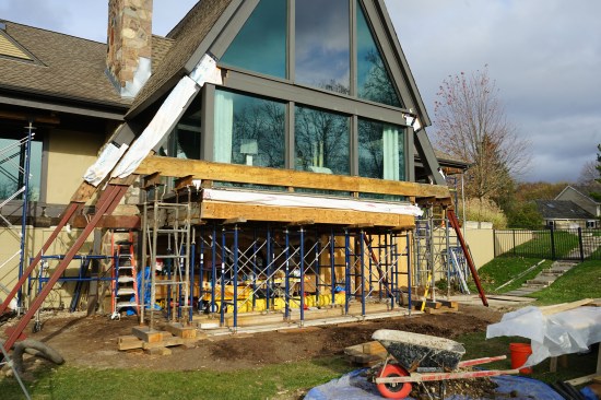
Given the tenuous condition of the existing structure and the possibility of the roof spreading as we unraveled the load path, we had to thoroughly shore up the home during the repair. This involved shoring under the entire A-frame floor, as well as erecting shoring towers on the right and left flanks of the A-frame where the main house roof extended over the deck. We also installed a temporary LVL beam across the face of the windows at the base of the triangular gable end.
Like many jobs on existing homes, our repair work touched a lot of the building systems. As seen in the slideshow “Preparing to Rework the Load Path” (above), several of the initial excavations for the helical piers had cable and electric lines crossing them, and one had a waste line that was directly in the path of the helical pier. A section of this pipe had to be removed to set the pier and then replaced once the pier was installed.
Rebuilding the Frame
1
of 15
After removing the rotted ledger and grinding off the corroded b…
After removing the rotted ledger and grinding off the corroded bolts, the author made the first cut to sever the connection between the flitch plate spliced into the rafters and the plate sandwiched between the ledger and the rim joist.
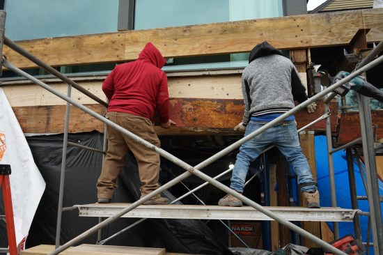
The flitch plates running along the bottom of the gable end were…
The flitch plates running along the bottom of the gable end were cut and removed in sections.
With the rim joist removed, shoring was added to support the flo…
With the rim joist removed, shoring was added to support the floor structure.
A new LVL beam to support a new rim joist was installed.
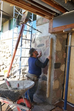
To support the new floor beam, the concrete slab had to be repai…
To support the new floor beam, the concrete slab had to be repaired and a new framing sill installed.
New joist hangers were installed to support the floor joists.
New LVL posts were installed to support the LVL beam.
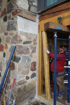
The author planed 2×10 stock to pack out the space between the n…
The author planed 2×10 stock to pack out the space between the new rim joist and the face of the new beam. It was much quicker and neater to plane down this material than it would have been to cut back all the floor joists to reposition the rim joist in relation to the windows.
Laying in the planed material to pack out the rim joist.
A new LVL was installed to support the windows on the right and …
A new LVL was installed to support the windows on the right and left of the gable end.
Once the deteriorated, let-in columns supporting this part of th…
Once the deteriorated, let-in columns supporting this part of the floor system were removed, the foundation had to be repaired with non-shrink grout.
New, built-up PSL columns were installed to support the LVL beam…
New, built-up PSL columns were installed to support the LVL beam.
A view of the new LVL beams and PSL columns on an outside corner…
A view of the new LVL beams and PSL columns on an outside corner.
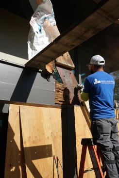
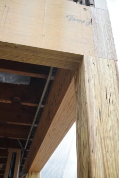
The nearly complete structure. All that remained were short wall…
The nearly complete structure. All that remained were short walls between the columns to support new windows and sheathing.
The photos in the slideshows show the crucial steps we took to complete the repair and reframe the enclosure. Our work will be followed by several contractors: One will remove all the windows and the remainder of the existing cladding and replace them with a modern WRB, new flashing, new insulated glass units, and new cladding; and a deck builder will rebuild the wrap-around deck.
JLC contributing editor Jake Lewandowski is a construction manager with his family’s business, Great Lakes Builders (greatlakesbuildersinc.com), which specializes in structural repairs in Greater Chicago. Follow him on Instagram: @jakemlewandowski