When my clients and their interior designer initially contacted us about a proposed addition, they had in mind a tall, tower-like structure with a vaulted ceiling and large windows overlooking their yard. During the design process, the project evolved into a larger space that included a small, conventional rectangular addition with a powder room and full basement joined to a faceted turret. While we considered designs ranging from eight-sided to 16-sided structures to fit within the circular footprint, we settled on a 12-sided dodecagon. This geometric shape seemed to offer the right number of segments for the window sizes and angle intensity that our clients envisioned.
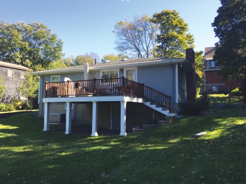
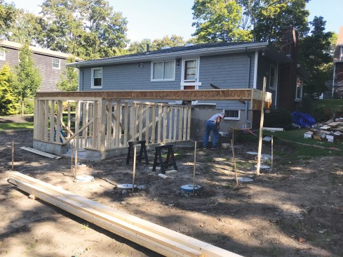
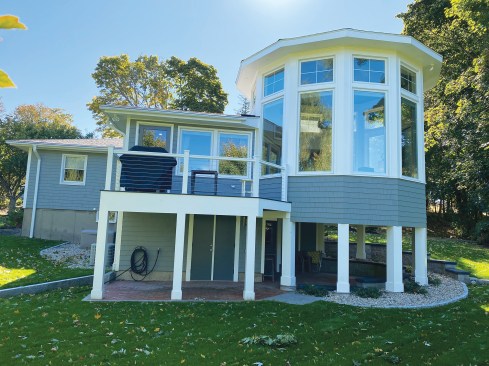
Prior to construction, the house had a modest footprint with a small, elevated deck overlooking the backyard.
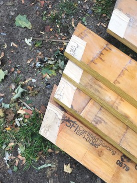
Knowing that we wanted the maximum amount of glass area possible per facet, I searched for the widest casement window available and found Marvin’s Ultimate clad casement window, which has a maximum size of 41 inches wide by 92 inches tall. To support the 13 foot 8 1/4 inch–tall wall needed to accommodate this window, the engineer specified double 5 1/4-by-5 1/4-inch PSL posts to be ripped to the dodecagon angle, then glued and screwed together with LedgerLok structural screws. Factoring in those dimensions with 2×6 jack studs determined the precise diameter of the dodecagon, which drove the rest of the design.
Going against our typical protocol, I decided to complete the construction documents on my own after my design partner Jay Rondeau finished the 3D conceptual design. On this project, I felt it would be important that the person who drew the dodecagon in CAD was the same one to lay it out in the field. It was critical to precisely draw in every 2×6, layer of sheathing, window frame, and so on and then be able to bring my laptop to the field and pull measurements from that drawing during layout and construction.
Foundation
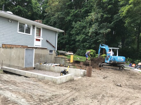
Because the foundation design needed to avoid disrupting a retaining wall and previous grading work to direct groundwater away from the basement, we decided to put the dodecagon on poured concrete piers—which probably also made the layout easier. First, though, we laid out and poured the rectangular portion of the addition. This was obviously the easy part, but it was also helpful, as it provided several measuring points for the dodecagon layout.
Tim Healey
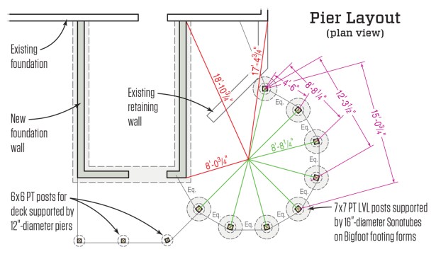
The author determined the center point of the dodecagon by pulling CAD measurements from three fixed points on the foundation (in red). A stake driven into the ground at this location acted as a fourth fixed control point for laying out the piers (in green). Measurements between pier locations taken from the CAD drawing (in purple) were used to double-check the layout and confirm that the footings were in exactly the right position.
Pier layout. Working with the excavator and foundation sub, David Davis of Davis and Sons Excavating, we found the center of the dodecagon by pulling the CAD measurements from three foundation points (shown in red in the illustration, above). There, we drove a stake into the ground as a fourth fixed control point to use for laying out the centers of the eight support piers (shown in green, above). We then double-checked all the measurements to the centers of the pier locations from the three foundation control points, as well as the measurements between piers.
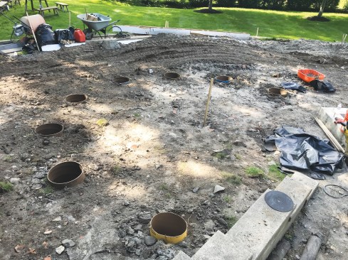
As we dug, set, and backfilled eight Bigfoot footing forms and cardboard tubes one by one, we constantly double-checked all measurements against the four control points, then against each other.
The project included a new foundation for a small rectangular addition, which provided two of the three control points that the author used to locate the center of the dodecagon, as described in the drawing above.
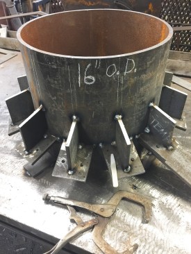
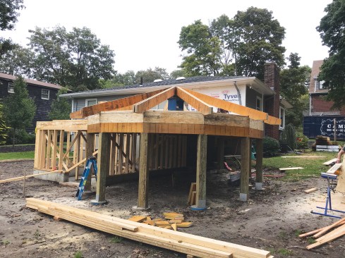
The dodecagon is supported in part by the addition foundation, and by eight 16-inch-diameter piers.
Concrete. We used a pump truck with a boom to reach over the house and place the concrete for the rectangular formed foundation. To transport the concrete from the truck to the backyard to fill the Bigfoot forms and three additional deck piers, we used a tracked Toro Mud Buggy, which has a capacity of a little more than 1/2 yard of concrete. We ordered an 8-yard load, enough to fill each dodecagon pier with about 0.85 cubic yard of concrete and each deck pier with about 0.35 cubic yard.

Each pier and the Bigfoot footing that supports it were reinforced with rebar and filled with a little less than a cubic yard of concrete.
Floor Framing
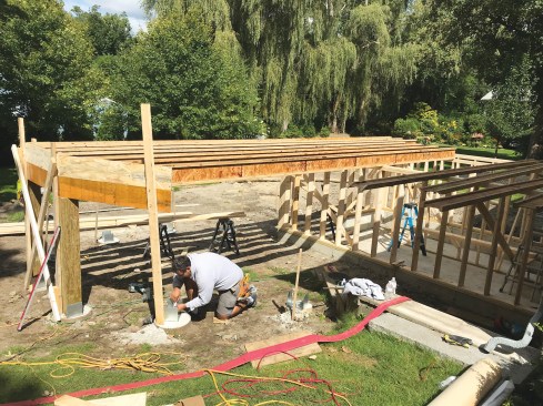
As with the foundation, it made sense to frame the rectangular portion of the addition first. This allowed us to install the floor system’s 9 1/2-inch I-joists, run them long where the footprints of the dodecagon and the rectangular addition overlapped, then cut the joists to fit the dodecagon shape after a careful layout.
Floor layout. The base of the first dodecagon segment that we framed was exactly parallel to the long walls of the rectangular addition. Per our CAD drawing, we determined the exact length of the long I-joists that would cantilever over the rectangular addition’s wall and extend into the dodecagon, then framed that segment first to use as a control for the rest of the dodecagon. We temporarily supported that segment as we installed its 9 1/2-inch LSL rim joist and triple 9 1/2-inch LVL girder, then measured and fit the 7×7 pressure-treated PSL posts that would support the assembly. Because of the many angles in the dodecagon, all the segments had to be exactly the same size, so prior to assembly we had precut all the material for the triple 9 1/2-inch LVL girders and LSL rim joists to length per the CAD drawing, production-style.
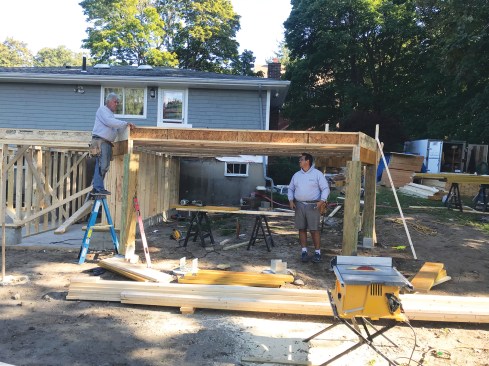
A temporary post supports the triple-LVL girder and LSL rim joist of the first segment of the dodecagon.
Then workers installed the first pair of permanent 7×7 PT PSL columns before moving on to the next segment.
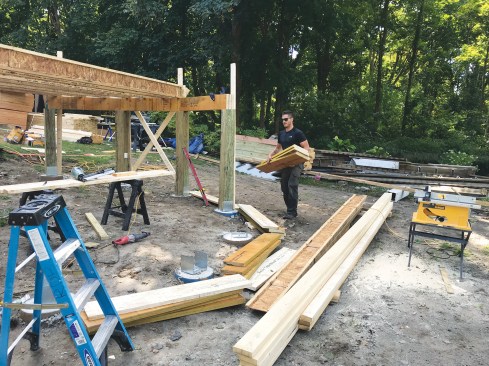
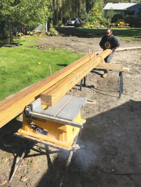
Workers precut all of the material needed to assemble the girders and rim joists per the CAD drawing.
To allow for adjustment, the girders, rim joists, and floor joists were only tacked in place during assembly.
We followed the same procedure as we framed the remaining segments, extending the floor joists following the measurements on the plans and assembling each segment’s rim joist and girder. We only tacked them in place with a couple of nails, though, so we’d be able to adjust their final position after the subfloor was installed. Then we propped up each segment temporarily to make sure it was level before cutting and fitting the next 7×7 post.
As we continued with the floor joist installation, we waited to lock down the metal post-base plates that connect the 7×7 posts to the piers. This allowed us to tweak each post’s final position after we had a chance to carefully check our layout on a plywood subfloor.
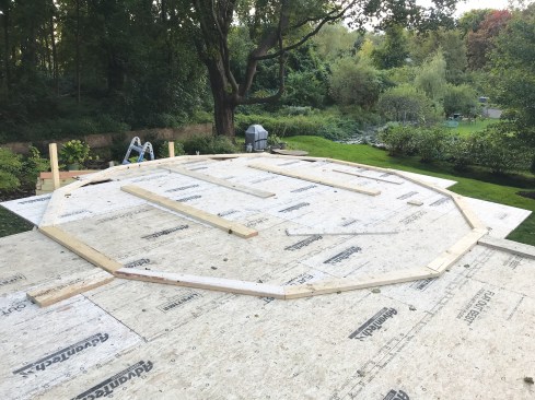
Subfloor. When installing the subfloor sheathing, we glued down and nailed off all the sheets over the rectangular addition but only dry-fit the plywood over the dodecagon. Working on the level rather than on the ground, we were able to locate the center point and lay out the dodecagon with more accuracy than when we were pouring the footings. We snapped perpendicular chalk lines that bisected two pairs of opposing segments and ran through the center of the dodecagon. Then we put a nail in the center and pulled measurements to the centers and corners of each segment to verify that they matched the plans and that all 12 sides were equal.
To complete the final, precise shape of the dodecagon, we cut 12 2×6 template plates to the exact same size, again per the CAD drawing. Following our chalked reference lines, we assembled the plates into an outline of the dodecagon on top of the sheathing, made slight adjustments to the segments and to the floor framing until we were happy with the layout, and marked the outline on the sheathing. Then we removed the 2×6 template plates and pulled up the sheathing so we could apply adhesive to the joists and nail the sheathing back down, running it long past the rim joists.
To finalize the layout, the crew assembled the dodecagon’s wall plates on top of the floor sheathing, which had been tacked in place, before tightening the bolts on the column base plates.
After installing the subfloor, we replaced the 2×6 templates on the completed subfloor, again checked the layout to make sure the reference lines marked on the sheathing aligned with the floor framing and rim joists underneath, and tacked the plates down to the sheathing. Using the plates as a guide, we cut out the final shape of the dodecagon on the plywood.
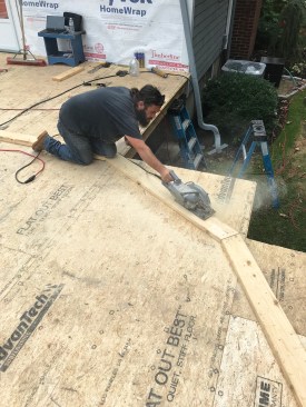
Once the author was satisfied that the wall plates, floor framing, and piers were aligned, workers finished fastening the sheathing to the framing and trimmed it to fit.
At this point, we were able to make final adjustments to the base plates connecting the 7×7 columns to the piers and finish nailing off the triple 9 1/2-inch girders and the 9 1/2-inch rim joists. To complete the assemblies, we fastened pairs of HL55 angle brackets to the top of each post to connect it to the girder it supports.
Rafter Prep
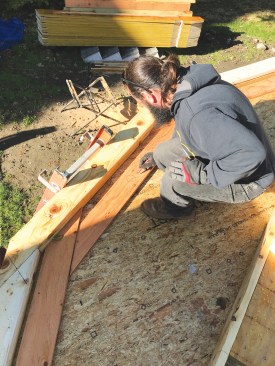
With a perfectly laid-out dodecagon on the subfloor and while we were close to the ground, we laid out, cut, and dry-fit the roof framing before framing the walls. Since the cathedral ceiling wouldn’t have any collar ties, the engineer specified a custom circular steel ridge with 12 seats at the 5:12 roof pitch for 12 double 9 1/2-inch LVL rafters. Each seat had a hole drilled through for a bolt to secure the rafter to the steel ridge. Working on the deck, we were able to comfortably determine the exact length of the rafters and height of the steel ridge above the top plate.
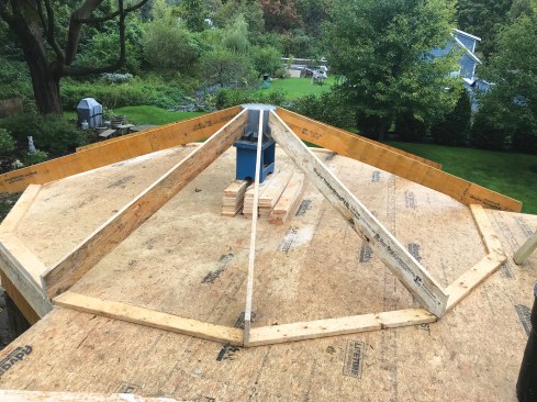
The dodecagon’s 12 double-LVL hip rafters hang from a custom-fabricated circular steel ridge (left). Working off the level floor deck made it easier to lay out the rafters (above).
Each of the rafter plumb cuts required a mortise to fit properly around the flanges at the steel ridge. We custom cut all the rafters, assembled and labeled them, and put them aside for later. We also saved the 2×6 dodecagon plate template to use for the top plate.
The plumb cuts where the rafters meet the ridge needed to be notched (left) to allow the rafters to fit over the connecting flanges at the ridge (above).
Wall Framing
We started by cutting all the dodecagon segment plates we would need to assemble the walls. There were more than usual, as we had decided to create a triple top plate by interlocking multiple layers of plywood and 2x6s. This would ensure that the top of the wall would never move.
The crew precut the top-plate components out of 2×6 stock and 3/4-inch plywood so that the triple top plate would interlock at the corners and tie the wall segments together.
Each wall segment consists of a pair of PSL corner posts ripped with a 15-degree bevel.
Each 13 foot 8 1/4 inch–tall wall segment consisted of two 5 1/4‑by-5 1/4-inch PSL corner posts, with one side of each post ripped to 15 degrees to create each 30-degree dodecagon corner. Because each of the eight full-height segments contained a lot of window area, there wasn’t much exterior wall sheathing to brace the structure. Instead, the engineered design called for the connections between the window jack-stud assembly (made up of a 2×6 and 3/4-inch CDX plywood ripped to 5 1/2 inches wide) and the PSL corner posts to be made with LedgerLok structural screws.
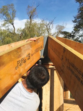
Along with the rest of the framing that made up each wall segment, the resulting assembly was quite heavy. A co-worker and I were barely able to lift one segment into position, so after we framed the rest of the walls on the ground, we summoned the remaining crew to help lift them up onto the deck and raise them.
We didn’t want to nail the dodecagon segments together until they were all raised, so we temporarily held them together with ratchet straps as we assembled the walls. This allowed us to check the layout with our precisely marked top plates.
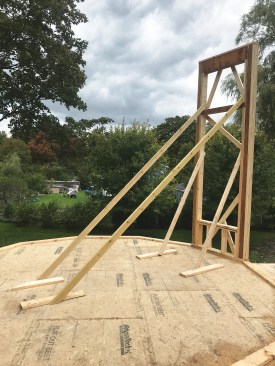
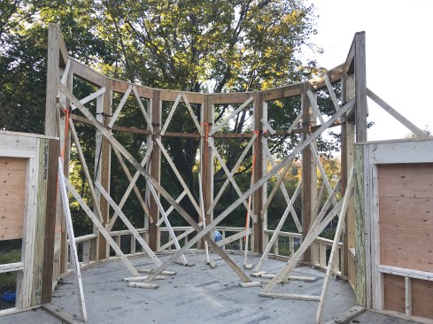
Bracing was used to support each wall section after it was erected (left), and straps were used to temporarily hold the eight tall wall sections together (above).
Four of the 12 wall segments are shorter, because they are located where the dodecagon overlaps the rectangular addition, and are supported by wall framing or by LVL girders buried in the addition’s ceiling framing. That meant that after raising the eight full-height segments, we needed to frame the rest of the addition’s walls and ceiling joists before continuing with the dodecagon. But at this point, we could secure the straps specified by the engineer to tie in the 7×7 columns on the base plate, the 9 1/2-inch triple LVL, rim joist, and newly raised 5 1/4-inch PSL wall corners. We left the plates of the remaining four segments on the subfloor so we could pull those measurements up and also mark out the layout for the hardwood floor.
One thing we wanted to avoid was having columns interrupt the interior space. The structural engineer, Alan Vitukevich of Aberjona Engineering, had cleverly designed one 24-foot-long (and heavy) triple 1 3/4-by-14-inch LVL beam that spans the entire length of the rectangular portion of the addition so that it would pick up loads from the roof structure on one of the three floating segments of the dodecagon that aren’t directly supported by a pier or by wall framing. Another triple 1 3/4-by-7 3/4-inch LVL beam connected to the first structural beam picks up the remaining roof loads, and on the other side, supports the center of the addition’s hip roof. Lastly, more triple 7 1/4-inch LVL girders finish the shape of the interior floating portion of the dodecagon roof, all supported by 5 1/4‑inch PSL columns framed within the exterior walls.
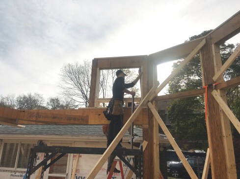
After the crew framed the floor system girders needed to support the shorter walls over the addition framing, the crew laid down a temporary floor system across the upper window openings that allowed them to finish installing the top plates and work on the roof framing.
Once the LVL supporting beams were in, we continued with the remaining dodecagon segments. These short segments were also framed with PSL corner posts with one side beveled 15 degrees.
When all 12 segment walls were installed, we built a temporary floor—to help us assemble the roof framing—by running 2×8 joists spanning the dodecagon through the upper windows. We positioned the precut 2×6 top plates on top of the walls, then used ratchet straps to adjust the wall positions relative to each other. The challenge was that moving one segment affected the others. To lock the walls in place once we had them in the right position, we kept the ratchet straps on until the rafters were installed and the roof sheathing was glued and nailed.
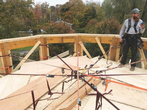
Working off the temporary floor, workers used ratchet straps between opposing pairs of wall posts to adjust the plate layout to its final position before starting roof framing.
Roof Framing
After the three layers of precut top plates had been glued and screwed together, the dodecagon shape perfectly matched the shape on the subfloor. Then, to support the steel ridge at the right elevation, we built a temporary seat out of 2x4s that had to be carefully positioned around the ratchet straps. With that, it was time to install all the precut roof rafters, using construction adhesive and 3-inch LedgerLoks to fasten the double hip rafters together.
At the steel ridge, the mortises that we had made at the top of each roof rafter allowed the double 9 1/2-inch hip rafter to sit around the steel flange on the seat it was designed for. We also used plenty of construction adhesive where the rafters meet the ridge and predrilled the hip rafters for 2 1/2-inch LedgerLoks that we drove up into the rafters through predrilled holes in the steel ridge. At the top plate, we installed custom-fabricated right-angle brackets specified by the engineer to reinforce the connection between the hip rafters and the top plate.
The hip rafters are connected to the steel circular ridge with structural screws driven up through holes in the ridge into each rafter.
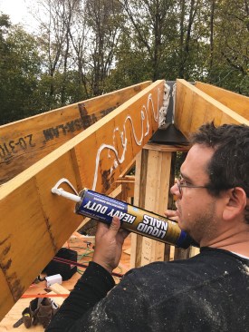
Construction adhesive and structural screws were used to join the double-LVL hip rafters together.
Once the roof rafters were complete, we nailed straps to the tops of the rafters over the steel ridge to further reduce chances of spreading. Then we installed 5/8-inch-thick roof sheathing.
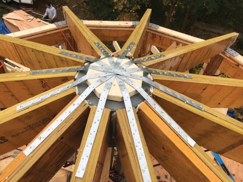
At the ridge, metal straps reinforce the connection between opposing rafters, while custom-fabricated brackets connect the hip rafters to the plates.
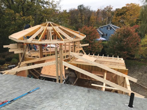
After the hip rafters were installed, the crew finished the roof framing by installing the common rafters, subfascia, and roof sheathing.
Sealing the Envelope
After we finished trimming the dodecagon’s eaves and installing the windows, the insulation sub filled the rafter bays in the ceiling with 7.1 inches of Icynene ProSeal LE closed-cell foam. This provides the vaulted and unventilated “hot” roof with an approved air barrier and R-49 insulation to meet local code requirements. To insulate and air-seal the turret’s floor system, the sub sprayed the joist bays with 4.3 inches of foam, for R-30 insulation. The walls received a minimum of 3 inches of foam, for R-21 insulation.
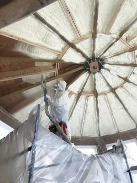
The dodecagon’s roof rafter bays and wall stud bays were insulated with closed-cell spray foam insulation.
To match the existing house, we clad the turret and addition with prefinished white cedar shingles after trimming the windows and columns with PVC. On the interior, the walls were given a smooth veneer-coat plaster finish over a blueboard substrate. On the ceiling, we installed painted tongue-and-groove beaded ceiling boards.
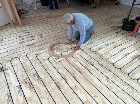
Over the subfloor, workers installed prerouted panels that accommodate tubing for a hydronic radiant heating system.
We installed Viega Climate Panels over the subfloor to accommodate the new addition’s radiant heating and cooling system. These are 1/2-inch-thick engineered wood panels with an aluminum backing designed to accept Viega’s 5/16-inch PEX tubing for hydronic radiant systems.
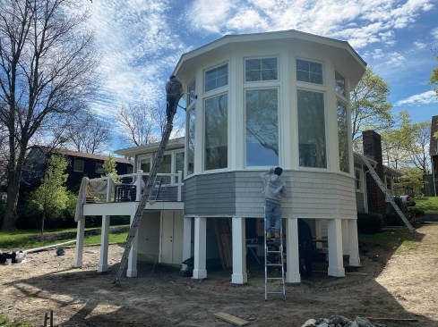
The exterior was finished with PVC trim and cedar shingle siding.
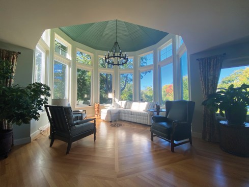
The interior features a rift-sawn white oak floor with a central compass-rose inlay.
To add a final distinctive touch to the room, our clients selected a round compass-rose inlay, which the flooring sub installed in the center of the dodecagon’s floor. The rift-sawn white-oak strip flooring was then installed in a pattern that matches the ceiling boards and emphasizes the 12 facets of the turret.
Photos by Adam Ricci.


