We recently were called in to repair trusses on a townhouse that was built in the mid-1990s.
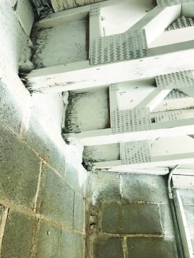
Removing water-damaged ceilings and walls revealed three trusses with rotted ends.
To reinforce them, the author made plywood gussets. He traced the chord pattern onto a blank.
My family has a structural repair business in the greater Chicago area, and we are often called in to repair damage caused by water leaking into a building. In my position as project manager, I am responsible for assessing the problem, coming up with a repair solution, and then making sure that the repairs are completed properly in the most efficient way, while being fair and honest to the client.
Damage from a roof leak. The trusses on this townhouse supported a third-floor deck with a living space below. After seeing water damage on some interior drywall, the clients opened up the wall below the trusses. When they found extensive mold, they removed the rest of the drywall, exposing an adjacent CMU wall with pockets that supported the trusses. The ends of three of the trusses had rotted.
After removing the ceiling drywall and finding more mold, the clients discovered that water had been coming in where the roof met the parapet wall. The contractor who had done all the work up to that point replaced the entire roof under the deck, including the sheathing. A mold-mitigation company cleaned away the mold and painted all the framing with white mold-resistant primer. An engineer was called in to assess the damage to the trusses, and we were called in to do the structural repair to the trusses.
Engineer’s specs. The engineer’s recommendations were specific. The trusses needed to be lifted to their original height and cut flush with the inside face of the CMU wall, with the rotted sections removed. To reinforce the ends of the trusses, 3/4-inch plywood gussets were to be attached to both sides of each truss with 10d nails 3 inches on-center on all chords. To keep the plywood from cupping under the load, 2×4 squash blocks were to be inserted between the top and bottom chords. Then MC 12 x 14.3 steel C-channel (12 inches tall and weighing 14.3 pounds per foot) needed to be fastened to the CMU wall below the trusses to support their load.
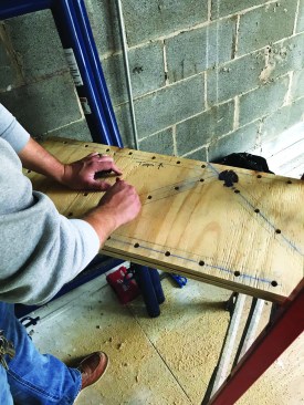
He made a template to transfer the fastener layout.
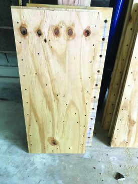
Plywood gussets. The first step was making the plywood gussets for the 15-inch-tall trusses. We cut blanks 15 by 36 inches out of 3/4-inch plywood with the grain running in the long direction. To ensure that we met the nailing schedule on all of the gussets, I made a fastener template by clamping one of the blanks to the side of a truss and tracing the outline of the truss chords. Then I plotted out the fastener locations and drilled a 1/2-inch-diameter hole at each location, big enough for a marking pen. With that pattern, we were able to quickly transfer the exact fastener locations to each of the six gussets.

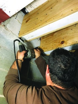
Squash blocks stiffened the ends of the trusses.
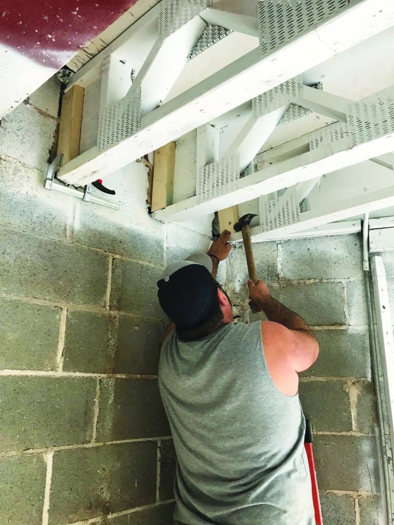
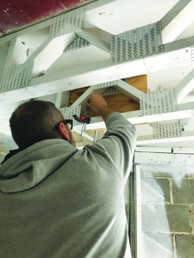
A palm nailer was used to drive the specified fasteners at each location to attach the gussets to the ends of the trusses.
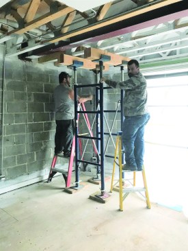
The crew used screw jacks and beams to lift the trusses to their original height.
Before attaching the gussets, we inserted the 2×4 squash blocks as specified by the engineer. We then clamped the gussets to the trusses and drove nails at each fastener location, using a palm nailer. With the gussets in place, we spanned across the underside of the trusses with beams and lifted them using a four-point screw jack assembly. When the trusses were at the proper height, we cut the rotted part off the ends with a reciprocating saw.
Then they cut away the rotted wood with a reciprocating saw.
Steel support. The channel specified by the engineer had a flange depth of 2.12 inches, which meant that the modified trusses would have only 2 1/8 inches of bearing. I needed to increase the bearing in a way that could be concealed by the contractor coming in after us to do the interior finish. Additionally, one of the trusses was in much worse shape than we had originally thought—with no solid wood until 8 1/2 inches from the end. So I called the engineer and asked if I could use sections of 1/2-inch plate welded to the channel to extend the bearing area. For two of the trusses, the plate would be 4 1/2 inches long; to adequately support the worst one, however, we’d need a 9 3/4-inch section. These sizes would provide enough length to support the trusses and to allow for drilling holes to lag the plates into the trusses.
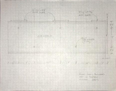
With an engineer's guidance, the author drew the support-beam elevation …
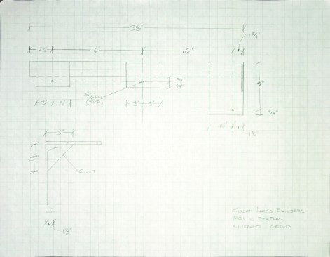
… plan, and section.
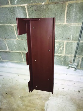
The author’s approved drawings guided the fabrication of the support beam.
The engineer specified adding a diagonal gusset to support the longest plate section, but he said I could put the gusset at the end of the channel to keep it concealed in the wall. Armed with all of this information, I drew up the beam with the supports, the gussets, and the fastener locations and sent the drawings to the engineer. After getting his approval, I gave the drawings to my steel fabricator, and he made up the support beam with the welded support plates. The drawings were pretty basic, but doing them gave me control over exactly how the beam would turn out, and it saved me the expense of hiring someone to draw the beam.
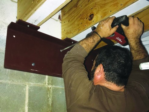
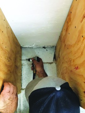
With the beam lag-bolted to the trusses, the crew drilled holes for the anchors.
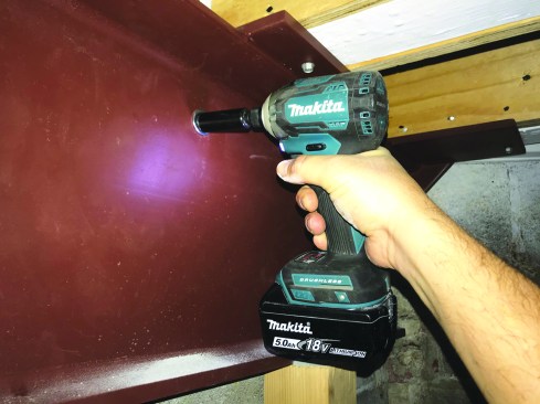
The anchors were first snugged with an impact driver.
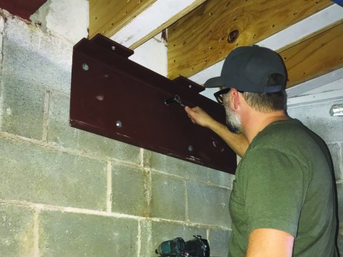
Installing the steel. The steel support beam arrived painted with a rust-resistant finish. Two crew members lifted the beam and held it in place under the trusses while I drove 1/4-inch lags into the trusses through holes drilled in the support plates. The lags held the beam in place temporarily while we fastened the vertical part of the beam to the CMU wall. At this point, the trusses were already at their final elevation, but to make sure that they wouldn’t drop a bit when we removed our temporary supports, we jacked a 4×4 post under the channel to keep it snug against the trusses.
The engineer specified 1/2-inch-by-2 1/4-inch Hilti HLC-H sleeve anchors to fasten the steel channel to the concrete block wall. I had laid out the fastener holes for the steel fabricator to ensure that the fasteners landed well clear of the mortar joints between the blocks.
Then they were given their final torque with a ratchet wrench.
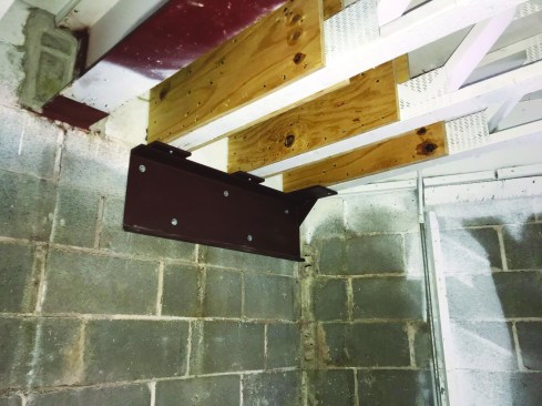
The final assembly will be concealed in the wall after the finishes are applied.
With the steel channel held firmly in place, we drilled holes for the sleeve anchors. After drilling the holes, we blew the dust and debris out of them and tapped the anchors into place. It is important not to overtighten sleeve anchors, so we first tightened them with an impact driver until they snugged up, then finished torquing the sleeve bolts by hand with a ratchet wrench. After removing the temporary supports under the trusses, we cleaned the jobsite thoroughly (we always try to leave the place cleaner than it was when we arrived). Our job as the structural repair crew was finished and the site was ready for the restoration crew to come in and reconstruct the interior finish.