Materials
The most common materials used to fabricate ducts are metal, fiberglass ductboard, and flexible wire-and-plastic “flex-duct.” All three materials can be used with good results, but size requirements vary from material to material because of differences in surface characteristics that affect resistance to airflow. Air-sealing and connection methods also vary between materials. Flex-duct and fiberglass ductboard may be self-insulating, whereas metal duct typically should have added insulation (see Insulating Ducts in Insulating and Air-Sealing).
Duct Sizing
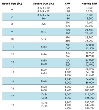
The size of supply and return registers (grilles), airflow capacity per room, and the size and layout of ductwork should all be determined by using ACCA Manual D (preferably, by using current computer software approved by the ACCA). Approximate sizing can be determined using the table below.
Balancing Supply and Return Air
Lengths, diameters, and grille sizes of return ducts should be specified using Manual D to ensure equal supply and return airflow. The volume and pressure of supply and return must match. Otherwise, rooms may be overpressurized or underpressurized, impeding the flow of heated or cooled air to rooms and increasing air leakage through cracks in the building envelope.
Total area of return grilles and supply grilles should be equal. The ideal setup is to provide a dedicated return duct for each room served by supply ducts. However, one or two large, centrally located return grilles per floor will function effectively, as long as free airflow is possible from room to room via undercut doors or transfer grilles.
Return location. A hallway location is preferable to a living room or similar spot, because air movement or noise near the grille may be noticeable. However, the location of return grilles has little effect on room airflow, except within one or two feet of the grille. High-wall, low-wall, ceiling, and floor locations work equally well. Return grilles will not cause or prevent drafts.
To reduce fan noise at return grilles, use sound-absorbing duct liners. When return duct runs are short, including two 90-degree bends in the run will help attenuate fan noise.
Supply Duct Layout
Common duct configurations include trunk-and-branch, radial, and perimeter loop (below).
Some systems may lay out most conveniently with a combination of these patterns.
Trunk-and-Branch Systems
In this setup, ducts to individual registers branch off from a long central spine. The large trunk duct can be made of metal or fiberglass duct board; branch ducts can be of metal or flex-duct.
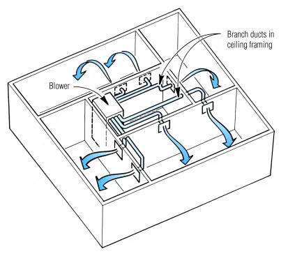
An efficient trunk-and-branch plenum consists of a centrally located blower that delivers air to a large trunk on either side. The blower may be located at one end of the trunk, but the trunk size must step down to equalize trunk-branch losses.
Extended plenum. The ideal trunk-and-branch system is laid out with the air handler at the center of the main trunk (Figure: Trunk-and-Branch System, A, above). That way, individual total duct runs are of similar length and airflow is roughly uniform at all outlets, even with a trunk duct of uniform diameter.
Reducing plenum. If the blower is at one end of a long run of trunk duct, airflow at the most distant registers will vary from the flow at the closest ones unless the trunk duct diameter is stepped down at a chosen midpoint (Figure: Trunk-and-Branch System, B, above, and below, A).
The trunk reduction should occur where calculated air velocity in the main duct drops to about 50% of the velocity near the blower.
In commercial systems, the main duct may be stepped down after each branch duct joint, using the “equal friction” method to calculate the reduction. This saves material and improves performance, but is costly in labor time and requires extra calculation.
Primary-secondary trunk. Trunk-and-branch systems for complicated house footprints may use more than one trunk, with a large primary trunk feeding one or more smaller secondary trunks (Figure 7-38B, page 160). A reducer tee joins the main trunk to the smaller trunks, serving the same function as the reducer fitting used in reduced-trunk setups.
Flex-duct. Trunk-and-branch systems can be economically built with a “box and flex-duct” method. In this system, large-diameter flex-duct trunks feed ductboard boxes that serve as attachment points for smaller flex-duct or metal duct runs to individual outlets.
Flex-duct bends and curves conveniently and works particularly well in attics; however, sharp bends and kinks must not be allowed because they will impede airflow. With flex-duct, allowance must always be made for increased internal friction of the spiral corrugations; a larger duct is usually needed when substituting flex-duct for metal duct.
Radial Systems
In a radial or “spider” duct setup, individual ducts run directly to outlets from a single short supply plenum (Figure: Radial and Perimeter-Loop Systems, A). With no trunk duct, radial systems are simple to install and inexpensive. The typical arrangement is comprised of ducts of equal lengths around a centrally located blower, but symmetry is not a requirement: With correct sizing of duct diameter, runs may vary in length as needed.
Slab homes often use rigid ducts buried in a radial pattern within the floor, because the low perimeter outlets provide good heating comfort. Because of potential moisture problems, ducts should never be located beneath concrete slabs. But a spider system can also work well when installed with flex-duct in an attic or crawlspace.
Perimeter-Loop Systems
For slab-on-grade foundations in a cold climate, a perimeter-loop system can provide the most comfortable floor in winter, because it warms the floor near the cold walls (Figure: Radial and Perimeter-Loop Systems, B). However, perimeter loops are considerably harder to design and more expensive to install.
Supply Register Layout
Supply registers must be sized to provide sufficient air to heat or cool each room, and placed to ensure good mixing of air before the warmed or cooled airstream contacts occupants.
Cooling climates. Where cooling is the primary purpose, ceiling diffusers or high sidewall registers provide the best result. Air thrown across the ceiling mixes gradually into room air and drops gently into occupied space.
High inside-wall outlets are practical in many building layouts, because the outlets can be readily served by ducts from a central supply trunk (below).
While it is convenient to run supply ducts from a central plenum, the air must be at sufficient velocity to reach outside walls. Comfort will be compromised if the air drops prematurely or is directed downward by ceiling height variations.
However, outlets must throw air far enough to reach the wall opposite the register. Ceiling diffusers in the center of the room may be able to reach all walls of the room with a lower initial air velocity, in some cases providing better comfort and quieter operation.
Mixed climates. If both cooling and heating are important, choose low-perimeter grilles directed upward. Studies and field experience have proven this to be a satisfactory compromise that provides good comfort in both heating and cooling seasons.
Heating climates. In climates where heating needs predominate over cooling needs, perimeter floor grilles or low-sidewall outlets with vanes that direct air up the sidewall are preferred. Locations beneath windows are optimal. The upward-directed airstream will mix with cool air next to the wall or window before contacting room occupants, moderate the chilling effect of the cold wall or window, and counteract the tendency of cold air to drop down wall surfaces by convection and collect at floor height.
Insulating and Air-Sealing

Energy codes require all heating and cooling ducts running through unconditioned space to be air sealed and insulated. In addition, the ducts will need to be tested to verify tightness.
Insulating Ducts
Wherever possible, run all ductwork within the conditioned envelope of the building. When you do, heating and cooling ducts do not have to be air sealed or insulated.
Per the 2012 IECC:
All supply ducts running through unconditioned attics must be insulated to a minimum R-8.
All other heating and cooling ducts running through unconditioned space must be insulated to a min. R-6.
Sealing Duct Joints
The figure below calls out critical air-leakage points that must be sealed. Make sure surfaces are clean and dry before applying tape: Use cleaner/degreaser if dirt or oil is present.
In addition to sealing duct joints, seal register boxes to the wall or floor with caulk or mastic and any penetrations in the air handler or plenums.
Metal Duct Joints. Mechanically fasten, clean, and seal all metal-to-metal connections.
- Use at least three equally spaced #8 screws to fasten round ducts that are up to 12 in. diameter, and five screws for ducts over 12 in. diameter.
- Use at least one screw per side for square or rectangular ducts.
- Crimp joints should have an overlap of at least 11/2 in.
- Seal openings greater than 1/16 in. with mastic and mesh or butyl adhesive tape. Mastic alone, or UL 181A-listed duct-sealing tape, can be used for gaps smaller than 1/16 in.
- Seal collar connections between ducts and boxes or plenums thoroughly with mastic or tape.
Watch this video for an example.
Fiberglass ductboard joints. Ductboard is typically joined at intersecting male and female ends on the boards, following manufacturer’s instructions.
The procedure usually involves these steps:
- Cut the metal vapor barrier at the corners of the female end and fold back.
- Join the male end to the female ends.
- Lap the vapor barrier and staple the flap closed
- Seal the connections with adhesive, mastic, or UL 181A-listed pressure-sensitive or heat-activated tape.
Watch this video for an example.
Flex duct joints. Flexible ducts should be joined by a metal sleeve, collar, or coupling:
- Extend fitting at least 2 in. into the inner core, leaving a 1-in. attachment area on the fitting for a tape seal.
- Mechanically attach the inner core to the fitting with a drawband over the inner core and fitting.
- If screws are used instead of a drawband, use #8 screws positioned to pin the wire coil of the inner liner to the
- fitting.
- Use at least three screws for duct material smaller than 12 in. diameter, and five screws for ducts larger than 12 in. diameter.
- Seal the inner core to the fitting with mastic or UL 181-compliant tape, and seal the outer vapor-barrier sleeve with a drawband and tape. Patch any holes or rips with mastic or tape.
- The inner core should be mechanically fastened to all fittings, preferably using drawbands installed directly over the inner core and beaded fitting.
- If beaded sleeves and collars are not used, then the inner core should be fastened to the fitting using #8 screws equally spaced around the diameter of the duct, and installed to capture the wire coil of the inner liner (three screws for ducts up to 12 in. diameter, and five screws for ducts over 12 in. diameter).
Watch this video for an example.
Duct Leakage Minimums
The energy code now requires that heating and cooling ducts be tested to verify duct tightness.
Post-construction testing. Code does allow duct testing after construction is complete. As of the 2012 IECC, total allowable duct leakage is 4 cfm per 100 sq.ft. of conditioned floor area. The problem with this test is that if you are above the limit, it is almost impossible to find and seal the leaks.
Rough-in testing. The same allowable total duct leakage of 4 cfm per 100 sq.ft. of conditioned floor area is required under the the 2012 IECC for testing after rough-in (before drywall), but at this stage fix can be readily tracked down and fixed. The test may done before the air handler is installed; in this case the limit for total duct leakage is 3 cfm per 100 sq.ft. of conditioned floor area.
Testing ducts takes one to two hours to accomplish. To test, technicians connect a powerful, metered and calibrated fan to the system at a return plenum or at the air handler, and then pressurize the system and measure airflow. A fog machine can be used to trace leaks. Companies supplying duct-testing equipment can also provide training for testers and information about applicable standards for airtightness.
Free-Standing Gas Heaters
Free-standing gas-fired heaters can be ideal for heating an addition or remodeled space, or for supplying heat to large connected areas in an open floor plan. They operate at efficiencies around 80% AFUE, but they can boost the home’s overall efficiency by serving as “load balancers.” The home can rely on the stove alone during swing seasons when the house requires little heat, switch to the central heating system during the main heating season, and use the stove to augment the central system during winter’s occasional coldest days. Many heaters offer variable output or thermostatic control. Capacities range from a minimum of about 5,000 BTU/hr to as high as 35,000 or 40,000 BTU/hr.
Some free-standing gas heaters are vented atmospherically through vertical B-vent, while others are designed for direct venting through coaxial vent pipe. Many units are capable of being vented either way.
- When atmospheric venting is chosen, makeup air is needed as for any other combustion appliance, and units should be tested for proper draft.
- If direct venting is used, clearance requirements for exterior vent terminations are the same as with any direct-vented heating equipment.
Air Conditioning Efficiency
Forced-air units used for circulating cooled air (central air conditioning) in southern climate zones are equipped with larger fans and use more electricity than in homes without air conditioning. In hot, humid climates, the efficiency of a system benefits from selecting a cooling system with a high Seasonal Energy Efficiency Ratio (at least 14.5) and with a variable-speed blower motor.
SEER
Most residential-sized (less than 5-ton) central air conditioners and heat pumps operating in the cooling mode are rated according to their seasonal energy efficiency ratio (SEER), which is the seasonal cooling output in BTUs divided by the seasonal energy input in watt-hours for an average U.S. climate. Pre-1992 central air conditioners may have SEER ratings of only 6 or 7. The national efficiency standard for central air conditioners in 2005 requires a minimum SEER of 10, but it will rise to SEER 13 for products manufactured after January 22, 2006.
SEER vs. EER
In addition to SEER, units are typically rated in EER — the ratio of the cooling output (in BTUs) divided by the power consumption (in watt-hours). SEER considers year-long operation (average load), whereas EER relates to maximum or full load. SEER gives an indication of energy (kwh) requirements of a unit, whereas EER gives an indication of demand (kw) needs.
A typical new room air conditioner has an EER of about 9.8. In general, larger-capacity air conditioners have higher efficiency, so central air conditioners are usually more efficient than room air conditioners. Look for an EER of 10.8 or higher for units of less than 20,000 BTU/hr.


