A number of carpentry jobs require repeating a series of precision moves. Building anything with louvers and making a wooden grid for a screen or floor register are examples that I have run into frequently in my carpentry career. These tasks can be quite painstaking in part because of all the repetitious steps, and in part because those steps require great precision. If you’re off by just a small fraction of an inch, you’re sunk; anyone’s eye can easily pick out off-parallel louvers or a slight variation in a closely spaced wooden grid.
With this type of work, I avoid doing a separate layout before making my cuts and instead build a jig that allows me to accurately position a router or saw at precise, repeatable increments. This not only saves the time of laying out each cut but also reduces the chances for introducing and compounding errors.

The author builds a jig that bridges across the top of a frame f…
Louvered Gable-End Vent
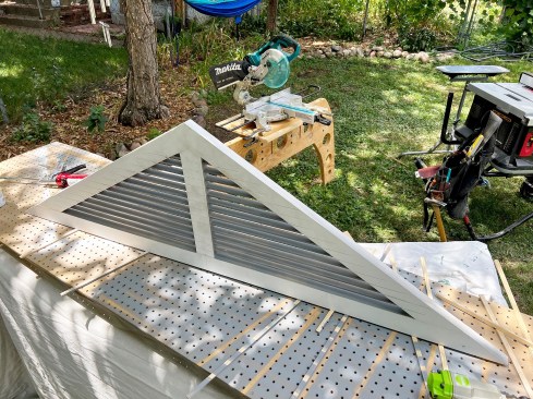
In my first example, I’ll describe the process I use for making louvered gable-end vents (see slideshow, above). In this case, we were matching an existing vent on the main house with one on a new addition, so an off-the-shelf vent product wasn’t going to work. For the triangular vent frame, we used 5/4 Windsor One Protected boards—the same material we were using for fascia and corner boards on the addition. A gable-end vent is usually fairly well protected by the rake overhang and doesn’t see a lot of weather. In addition, it ventilates (obviously), so it will dry if it does get wet. But I still want to use a durable material for long-term performance.
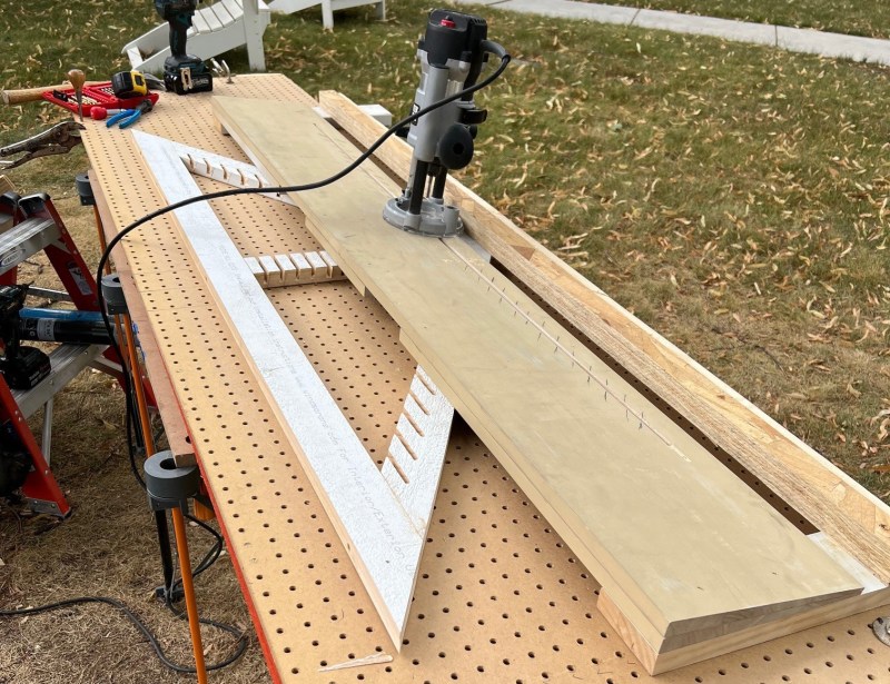
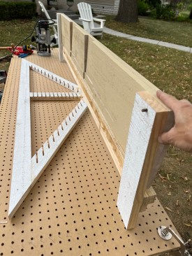
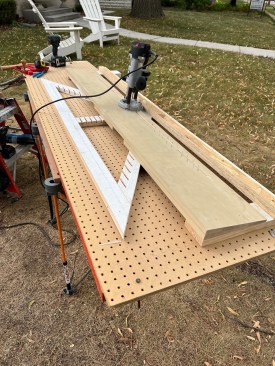
To make the vent, I started by setting up a worktable made of standard pegboard, which has a grid of holes on 1-inch centers. Two layers of pegboard with the holes aligned provide enough support for accurately and securely positioning 1/4-inch or 6mm shelf pins. I made a jig out of the same Windsor One material that would bridge across the triangular vent. I aligned this frame for the first mortise location, and carefully squared it to the pegboard and pinned it down with an 18-gauge nailer. With two shelf pins on the bottom surface of the jig, I could position it on the pegboard and advance it at even increments for each mortise I needed to cut in the frame to hold the louvers.
The top surface of the jig was constructed of two layers of beveled siding (the same material we were using to side the addition). The thick part of the beveled material faced toward the bottom of the vent, which angled the router so that the mortises would slant down from back to front, letting the louvers drain to the outside. Only the top layer of the beveled surface needs to be continuous; on the bottom, I used short scraps. (If you want a steeper angle, you could cut wedges to insert beneath the top layer, but be aware that the length of the mortising bit is a limiting factor on how deep the mortise can be.)
I cut a slot in the top surface of the siding near the short point of the bevel, and by running a plunge router with a straight mortising bit down the slot, I was able to cut angled mortises in each of the three pieces of the vent frame—in a single run across the frame for each louver.
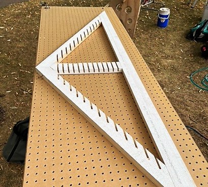
I made tick marks along the slot to indicate the beginning and end of each mortise run, which got shorter in length as I advanced up the triangular frame. I could have also drawn a line on the angled sides of the vent to indicate the stop and start points for each mortise line. The ends of the mortises don’t have to be super-precise because they are on the back of the frame and will never be visible. What is critical are the depth and width of the mortises, which need to hold the louvers securely at the same angle and at the same distance from each other so they are parallel and evenly spaced.
I cut my mortises about 7/8 inch deep, which left a full 1/4 inch from the bottom of the mortise to the front face of the 1 1/16-inch-thick frame (the mortise is angled, so the remainder is a little thicker than it would be for a straight mortise). I ripped the louvers to width afterward, so they were flush with the back of the frame. This allowed us to staple bug screen over the back before installing the vent, to reduce the number of hornets and other insects taking up residency in the attic.
One important point when using pegboard: I mark an “X” next to each hole I use to keep track of where I am on the pegboard surface as I move the jig across it. It’s easy to get cross-eyed looking at all those holes and be unsure of which ones you’ve used. By being methodical and making those tick marks to map my progress after each pass, I saved myself from mis-cutting a mortise at an uneven distance—the sort of mistake that typically happens near the end of a job to make the heartbreak even greater.
Once the frame and jig were made, cutting the mortises took only about 15 minutes. So the actual work was incredibly fast, but the set-up time is relatively long. That sort of job pacing is something you need to get used to with jobs like this.
Rectangular Units
We did a similar job—making reproduction fixed-louver shutters—that was also covered in JLC (see “Replacement Shutters Made Simpler,” May/11). As with the vent described above, we used an indexing jig. This one, however, took about three hours to set up and calibrate. And the shutter job was different in that all the mortises—all 500 of them, which we were able to complete in one afternoon once we finished building the jig—were identical, because we were building rectangular units with louvers that were all the same length.
In that case, we set the shelf pins at the ends of each shutter stile and moved the workpieces (the shutter stiles) while keeping the router at a fixed angle, and we used blocks to stop the router at each end of the short mortises. In contrast, for the gable-end vent, moving the router over a fixed workpiece and using a full pegboard surface was better suited to adjusting the length of each mortise run.
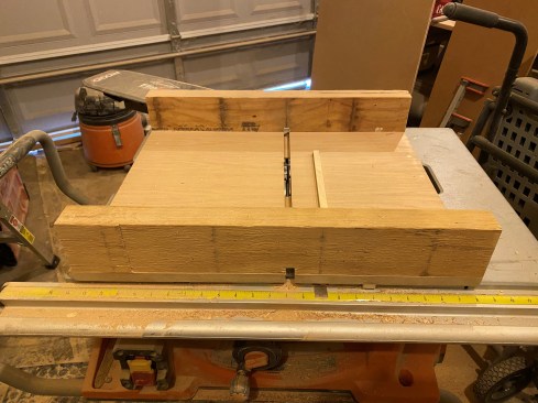
The author uses a table-saw sled with a cleat fixed to the plywood that’s the same width as the dado. The cleat is placed at the distance between successive dado cuts (in this case about 4 inches for an adjustable shelf system).
Self-Indexing Jigs
A variation on the process of using indexing pins that register to a pegboard surface (like we used for the gable-end vent) or to a series of reference holes (like we did with the replacement shutters) makes use of “self-indexing”—a method that indexes each new cut off one of the cuts you made previously. A simple version is a table-saw sled with a self-indexing cleat (see image above). Using a dado blade on the saw, you can cut one shelf mortise across a side panel, then lift the workpiece up, slide it over, lock it down onto the cleat, and make your next pass. I used this sled for cutting tool storage units that had dadoes in the side panels spaced every 4 inches. This allowed me to adjust the position of the shelves to fit a wide variety of toolboxes.
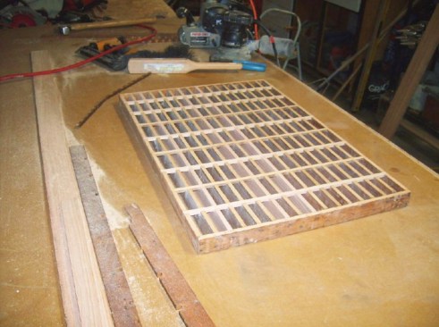
This HVAC floor register (above) was restored using a cleat system on a table-saw sled like the one shown previously. A similar method can also be used for making a Craftsman-style screen like the one shown at right.
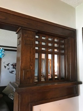
I used a similar sled with a self-indexing cleat for cutting the many cross laps in both the “joists” (long members) and “purlins” (shorter cross members) of a heat register that sat flush in a hardwood floor. I would use a similar process to make the grid for a Craftsman-style screen like the one shown above. For this type of work, I line up the members and cut each row of cross laps in one pass. It takes a little longer to align the pieces and shim them to fit tightly in the sled, but it ensures that each run is cut in a perfectly straight line.