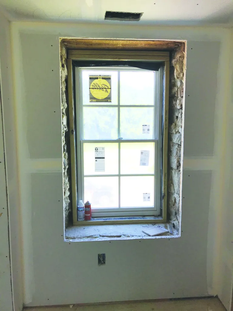
I have been trimming windows since my early teens. But when I saw these windows, I knew that they had the potential to be something special. The rubble stone walls of the 230-year-old farmhouse were roughly 18 inches thick, and the new windows were set flush with the outside. Wood framing on the inside of the walls brought the total wall thickness to about 2 feet. My job was to fabricate custom trims to dress up the irregular window wells.
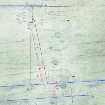
Planning. Because of variations in the thickness of the stone walls, the depths and widths of the rough openings varied significantly from window to window. So at the corner of each window opening, I measured from the frame of the bare window (ordered without jamb extensions) to the finish surface of the drywall. I also marked the centers of each window on the interior face of the bottom window jamb. With the tongue of a framing square held against the jambs, I transferred those centerlines to the drywall.
From those marks, I measured left and right to the drywall to determine the interior rough openings (the left and right numbers were rarely the same). From the smaller of the two measurements, I subtracted 5/16 inch (for shimming) and doubled the result, giving me the width (on the interior side) of the trim assembly for each window. As a result, the frame-and-panel-style side jamb extensions would flare open towards the interior 10 degrees.
Nielsen Crist
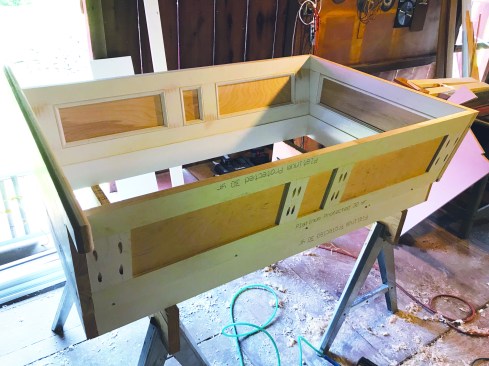
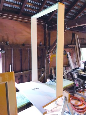
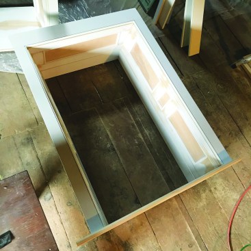
In the shop, the author prebuilt custom window-well trim.
Nielsen Crist
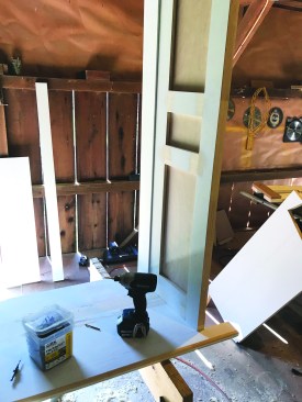
He built one for every opening …
Nielsen Crist
… sizing each to fit precisely.
I planned to use 5/4 stock for the stool, with a 1/2-inch rabbet cut along the bottom edge to allow it to bear on the window frame. Both the applied jambs and the frame-and-panel jamb extensions would have 1/4-inch reveals, while I chose a 3/16-inch reveal on the interior edge of the panel extensions, at the casings. The heights of the window rough openings were slightly larger than normal; this was simple to cover with the casing.
Nielsen Crist
The author drew full-scale drawings of the trim panels on each window stool.
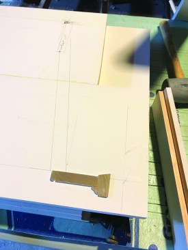
Stool layout. The first step in the actual construction of the window trim unit was to glue up the window stool so that it was deep enough to reach from the jamb of the window to the nosing of the sill beyond the plane of the drywall. I removed the primer from the adjoining edges of primed 5/4-by-12-inch finger-jointed pine with a planer. Then I glued those two pieces together, reinforcing the joint with Festool Domino Tenons as well as pocket-hole screws.
As soon as the two 5/4-by-12-inch pieces were joined, I drew a full-scale plan view of the sides on the window stool to establish the overall width of the stool. A centerline drawn across the glued-up boards (representing the centerline of the window) served as a reference.
Nielsen Crist
He laid thin wafers of the chosen moldings on each drawing.
Nielsen Crist
This determined the dimensions of the overhanging horns of the stool.
At the interior edge of the stool, I marked the overall width of the trim unit, as measured from the centerline. The beaded 3/4-inch-by-3 1/2-inch window casings would have a backband, so to lay out the window stool, I cut 1/4-inch-thick slices of the selected moldings and laid them in place on the stool. The casing would reveal 3/16 inch of the interior edge of the panels, while the horns (ears) of the stool would extend 1 inch wider than the outer edge of the casing backband, determining the overall width of the window stool. I wanted the stool to project into the room 1 inch farther than the backband, which in turn would project inwards 1 3/8 inch from the drywall, to create an even reveal on the stool at the front and outside edge of the casing. This meant that the interior edge of the window stool should project into the room 2 3/8 inches.
So now I had the outside dimension of the side panels of the trim unit at the interior edge, and I had the inside dimension of the side panels of the trim unit at the window edge. Next, I needed to locate (on my full-scale drawing) the distance between the interior edge of the window jamb and the drywall. I had measured the distance between the corners of the window jamb and the surface of the drywall. In plan view, I then drew the location of the interior edge of the window on the stool.

Nielsen Crist
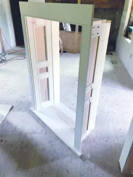
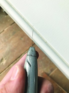
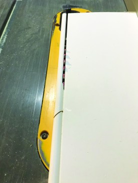
The trim pieces were assembled using glue, trim screws, …
Nielsen Crist
… pocket screws, and Festool Dominos.
Jamb extensions. The windows had been set in a rough 2×8 PT frame, which was fastened to the antique masonry. Therefore, the windows were not perfectly parallel to the plane of the drywall. To absorb these discrepancies, I used typical 1-by jamb extensions (which were also part of the prebuilt assembly) coming straight back from the window jamb. In order to clear the treated rough framing behind them, the 1-by jamb extensions needed a minimum depth of 4 7/8 inches. And depending on how far the window was out of parallel with the plane of the drywall, these parts were sometimes quite tapered and were cut using a track saw.
Nielsen Crist
Jamb extensions came straight back from the windows.
Nielsen Crist
They were were joined to side panels at about a 10-degree angle.
I cut rabbets into the edges of the panels at the jamb extensions, which allowed me to maintain a 1/4-inch reveal on the visible edge of the jamb extensions. The sides on the units flared outwards 10 degrees, so the rabbet cut on the edge of the side panels is angled. I made this with two passes on the table saw with the blade beveled at 10 degrees, so that I could screw it to the back of the 1-by jamb extensions with 1-inch-pan-head screws.
The sides each have three flat panels, with the height of the center flat panel centered on the top rail of the bottom sash of the window. This resulted in the upper panel being a shade taller than the lower. The 5/4 material making up the stiles and rails of the panels allowed for solid connections at both the 1-by extension edge (the rabbeted edge) as well as the jack-mitered beaded casing.
Nielsen Crist
Window casings were jack-mitered …
Nielsen Crist
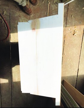
I cut the panels from 1/4-inch birch plywood to reduce weight, and sized them so that they would be a shade smaller than the 9/16-inch-deep slot cut in the inner edges of the rails and stiles. The slot was cut 7/16 inch from the face of the panels, which allowed the nose of the 3/4-inch nose-and-cove molding lining the panels to project proud of the rails and stiles.
Each unique trapezoidal top panel was laid out using the shape of the window stool for that particular unit for reference.
Nielsen Crist
Then the casings were fastened to the side panels using 18-gauge pneumatic brad nails and trim screws.
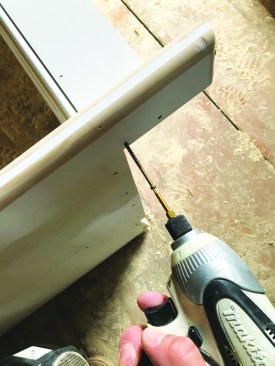
Installation. I fastened the 1-by jamb extensions and the panels to each other and to the stool with GRK trim screws. After jack-mitering the joints on the beaded casing, I fastened the head casings to the side casings with pocket screws. Then I fastened the casings to the extensions using glue and 18-gauge brad nails, along with trim screws driven in from underneath the stool.
When we carried each labeled window trim unit to its particular location and installed it, the units pretty much located themselves on the lip of the window jamb. Then I fastened the unit to the rough framing with GRK 3 1/8-inch RT trim screws driven through the 1-by jamb extensions, which allowed me to move the 1-by left or right to make the reveals of the window jamb consistent. Finally, I applied the backband molding to finish up the installation.


