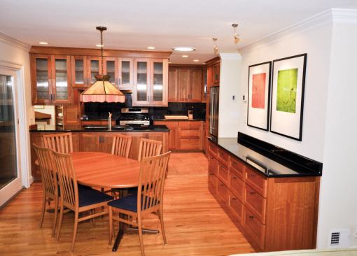
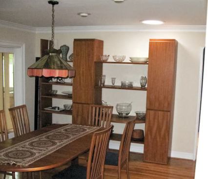
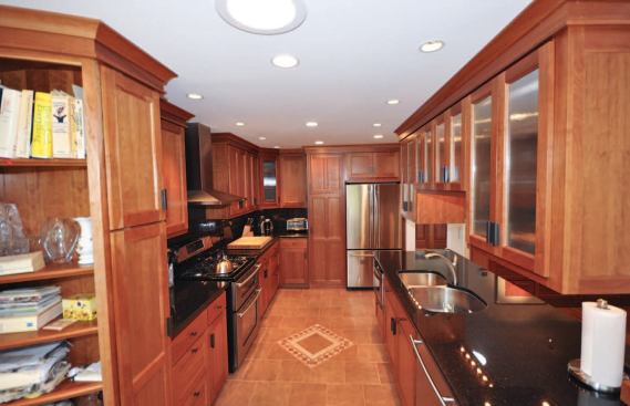
We were wrapping up the latest in a series of renovation projects on a suburban Maryland split-level home when I casually mentioned to the owner that her Thanksgiving family gatherings would be a lot more enjoyable if her small kitchen weren’t separated from the dining and living areas by a wall. “Can we get rid of it?” she asked. That brief exchange led to the kitchen renovation described in this article.
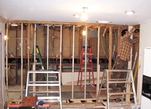
The wall was supporting significant roof loads, so removing it would involve some structural work. Our client also wanted a new radiant tile floor to match the one we’d already installed in the adjacent sunroom. But the existing tile was riddled with cracks, so before we installed the electric heat mat and new porcelain tile, we would need to reinforce the floor joists and beef up the subfloor.
Flitch Beams
To help with the structural work, I decided to make a contour map of existing conditions; that way, we could gauge any settling and bring finishes back to their original elevations if necessary. The living room would mostly remain untouched during demolition, so we set up a laser there, projected a level line, and measured up to the ceiling and down to the floor in a number of locations. We recorded these data points on the walls and on a plan view sketch, and referred to them often throughout the project.
The kitchen designer originally wanted us to simply replace the bearing wall with a dropped beam that would be partly buried in an upper peninsula cabinet. But cabinetmaker Joe Zabkar suggested we install a flush beam instead to simplify cabinet construction and create a stronger visual connection between the kitchen and dining area. That would entail considerably more work but would result in a much better-looking kitchen.
View Drawing, p. 3
-
DownloadExpanding a Kitchen
 (1249kb)
Structural Details
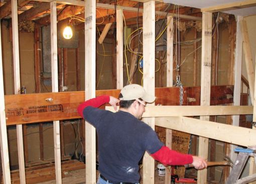
Working from the engineer’s stamped drawing, we assembled a flitch beam using two 1 3/4-inch-by-9 1/2-inch LVLs sandwiched around a length of 1/2-inch-by-9-inch steel. We built temporary shoring walls in the basement, kitchen, dining room, and attic to hold up the ceiling and roof while we removed the bearing wall and cut back the ceiling joists. We hoisted the 400-pound beam into position with the help of a pair of come-alongs rigged up in the attic. Each end of the flitch beam bears on a new Parallam PSL column.
Stiffening the Floor Framing
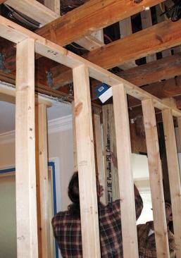
With the beam in place and the ceiling joists supported in hangers, we removed the temporary support walls, stripped off the existing floor sheathing, and pulled out any wiring and ductwork that was in the way. The plan called for 3/8-inch-by-7-inch steel plates the full length of the joists supporting the Parallam posts; this would both reinforce these joists and provide the compressive strength needed to transfer the roof loads from the posts through the joists. We installed the plates so that they bore directly on the existing steel I-beam girder below and added 2-by squash blocks underneath the columns, per the plans.
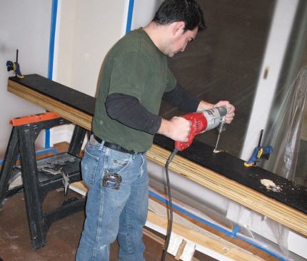
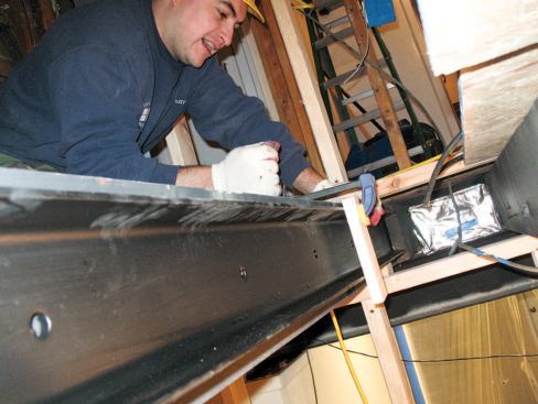
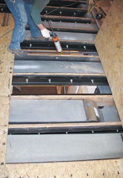
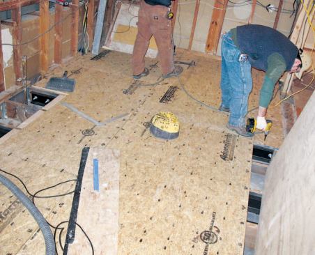
We reinforced the rest of the joists with C5x9 steel channel attached with 1/2-inch-diameter bolts spaced 12 inches on-center. These C-shaped channels are sized a little narrower than the existing 2×10 floor joists, so maneuvering them into position was easier than working with sistered wood joists; also, they’re more effective at limiting deflection.To further strengthen the floor, we replaced the existing subfloor with 3/4-inch AdvanTech T&G sheathing, followed by a layer of 1/2-inch plywood installed with full-spread Titebond wood glue. We fastened the second layer of sheathing to the first with 1 1/4-inch-long Grabber subfloor screws (800/477-8876, grabberman.com) spaced 8 inches apart; these fasteners are far more effective than drywall screws at drawing the layers together.
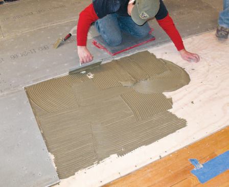
Backerboard. To prepare the floor for the heat mat and tile, we screwed 1/4-inch cement backerboard to the plywood, first bedding it in thinset mortar. We did this because we were planning to use a self-leveling underlayment (SLU) in conjunction with the heat mat. Usually, expanded metal lath is required when an SLU is poured over a wood subfloor (see “Working With Self-Leveling Underlayments,” 4/11). However, according to Laticrete – manufacturer of the self-leveling compound, thinset, heat mat, and grout we used on this project – a heat mat is an acceptable alternative to metal lath. Expanded metal lath can’t be used with a heat mat, of course, but in its absence we felt that the backerboard would provide a more stable substrate for the SLU than plywood alone.
Before installing the heat mat, we taped the backerboard joints with alkali-resistant fiberglass mesh and skim-coated the surface with thinset (a good way to use up partial bags of thinset from previous jobs). After the thinset cured, we rolled on a coat of SLU primer.
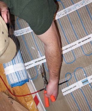
Heat mat. We’ve used electric heating mats from a number of different manufacturers but have come to prefer Laticrete’s Floor Heat Mat system (800/243-4788, laticrete.com). After we send a drawing of the floor to the distributor, Laticrete lays out the mat combinations using stock sizes and provides both a cutting diagram and a photo showing how the cut-out sections should be laid out. Compared with other systems – which can take weeks for delivery – turnaround time is very quick, usually no more than three days.
We needed two 1.5-foot-by-30-foot 240-volt mats to cover 100 square feet of floor area. Since sizing wiring and circuits for in-floor electric radiant heat can be tricky, I always work closely with my electrician at this stage.
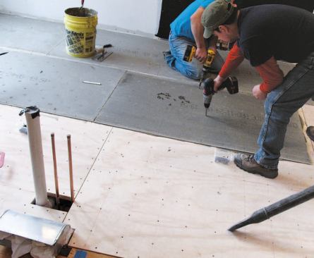
After snapping layout lines on the floors for the cabinetry, we cut the mats and put them in place. Even though they have self-adhesive backing, we also used duct-tape “Band-Aids” and some thinset to hold them and the wiring in place until we poured the SLU. Then we double-checked the wiring continuity with a multi-tester before giving the installation another coat of SLU primer, using a brush to agitate the primer and make sure the mats were adequately covered.
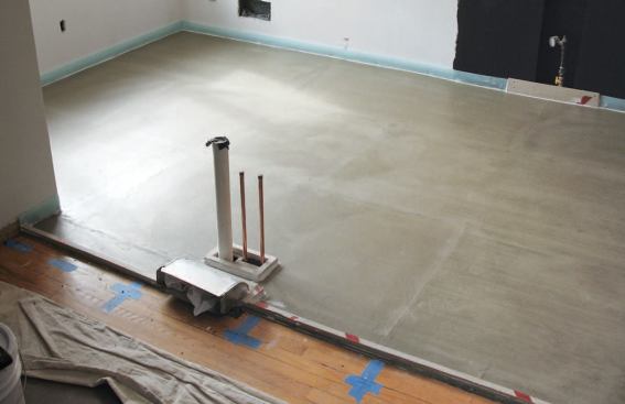
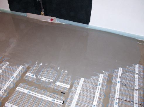
Once the primer was dry and we had checked once again for continuity, we poured a 3/8- to 1/2-inch-thick layer of SLU over the heat mats. Before tiling, we also rolled a thin primer coat and two full coats of Laticrete’s Hydro Ban liquid waterproofing and crack isolation membrane over the cured SLU.
Cabinetry
Normally, we like to install floor tile before the cabinetry. But this project featured two full-height cabinets, and we were worried that we might run into clearance problems when we tilted the cabinets into position from the horizontal to vertical position. Because we’d raised the elevation of the floor with the backerboard and SLU, and had dropped the ceiling elevation slightly with an added layer of 1/2-inch plywood under the drywall (to simplify can-light installation), actual clearances were less than the cabinetmaker had anticipated when he built the cabinets. So, to gain a little room, we opted to hold off on the tile installation until after the cabinetry was installed.
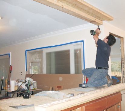
The big double-sided cherry cabinet hanging above the peninsula sink base isn’t the largest cabinet we’ve ever hung from a ceiling. But we knew it would be plenty heavy once the glass doors were attached and the shelves were loaded up with china and stemware. To install it, we first fastened a 3/4-inch-thick AdvanTech cleat to the ceiling framing and new flitch beam (Figure 6). We used 1/4-inch-diameter GRK RSS structural screws (800/263-0463, grkfasteners.com), which have over 900 pounds of withdrawal resistance per inch of penetration. Then we fastened 2×6 cleats to the AdvanTech, again using RSS screws and spreading construction adhesive onto each 2-by. To make fitting easier, we sized the cleats only about 1/8 inch less on each side than the interior cabinet dimensions, and we carefully shimmed the cleats so that they were plumb, level, and square.
After blocking the cabinet up into position, we fastened it to the cleats with RSS screws driven through predrilled holes in the upper rails. Field-applied crown mold covers the holes and the gap between the upper cabinets and the ceiling.
Cost
The structural work in the kitchen boosted the project budget by about $8,000, including $2,200 for the steel flitch plates and C-channel and another $1,000 for the engineering. Heat-mat installation accounted for roughly $2,500 – $500 each for the two 50-square-foot heat mats, $150 for the programmable thermostat, $300 to wire the new 240-volt electrical circuit, and about $1,000 in labor. And prepping the floor for tile cost almost $2,000 – $1,300 in materials and labor to pour 15 bags of self-leveling compound over the heat mat, and $700 to apply the Hydro Ban waterproofing membrane.
Rob Zschoche is a remodeling contractor in Chantilly, Va.


