My education in layout began in a large manufacturing and repair shop for machinery. For six months, I was apprenticed to a layout specialist who taught me how to plot accurate layout and machining lines on rough iron castings. Almost 45 years later, I still use the skills I learned on rough castings, applying them to the not-so-perfect floors, walls, countertops, and ceilings I have to cover with tile. Most layouts are simple, with only a few lines required to guide the tiles; but some can be quite complex, requiring a lot of thought, patience, and time to plot.
For tile installation, I use the term “layout” to refer not just to a set of chalk lines, but also to an entire systematic process. Whether the job is simple or complicated, there are two main goals behind the layout process. The first is to provide an accurate framework of chalk, pencil, or laser lines to guide the placement of tiles. The second is to improve the efficiency of the installation by eliminating unnecessary steps. In this article I will concentrate mainly on layout techniques for floors, but I use many of the same principles and tools for any tile layout.
CHECK THE FLOOR FOR FLAT AND LEVEL
For all tile layouts, including floors, I depend on a few tools: An accurate measuring tape, a framing square, a large 3-4-5 folding square, straightedges, a chalk line, and a laser square. I check all these tools regularly for accuracy.
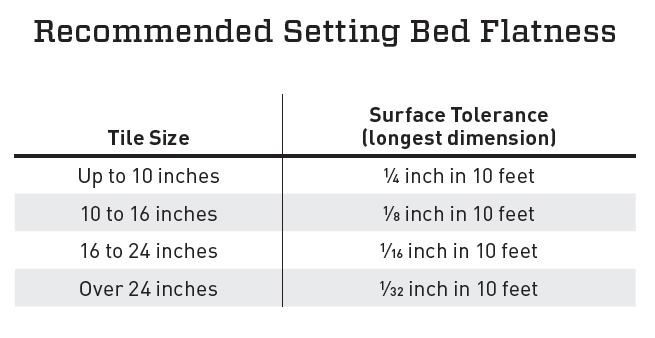
Before lasers arrived on the scene, I checked for flatness using 5- and 10-foot straightedges. This method is accurate if done carefully, and I still often use it on jobs of around 100 square feet or less. To check a floor manually, I use a straightedge and spirit level to determine if the surface is level and if it is flat enough for the size tile I’m installing (see Recommended Setting Bed Flatness, below). For floors larger than 100 square feet, I use a 10-foot straightedge because it corresponds to the industry standard of flat to within 1/4 inch in 10 feet. If there are any gaps greater than 1/4 inch between the straightedge and the surface, I know instantly that it is off-spec. For dimensions shorter than 10 feet, I use a 5-foot straightedge and look for gaps greater than 1/8 inch. I can use the same straightedges to check for the tighter tolerances that apply to larger tiles.
The pattern I use to check for flatness is simple and straightforward. I start by holding the straightedge against the floor, about one foot from the base of the wall, checking with the straightedge every foot across the length of the floor. After checking the floor in one direction, I rotate the straightedge 90° and repeat the steps above to check the floor in the other direction. Using a spirit level with the straightedge lets me check for level at the same time. The industry minimum standard is level to within 1/4 inch in 10 feet, but there can be exceptions either way. While I have the straightedge in my hands, I also check the walls around the perimeter of the floor for straightness. If the wall has a bow or waviness, I will have to compensate for it in my layout.
Though I still rely on straightedges and spirit levels during installation, they are tedious, cumbersome, and inaccurate when laying out large residential and commercial floor projects. Contractor-grade cross lasers (both horizontal and vertical beams) have taken a lead role in speeding up the work; lasers can significantly reduce the amount of time an installer spends measuring a surface, plotting layout lines, and checking tile alignment.
When I need to check a single- or multi-room floor layout for level and flatness, I use a laser and note changes in elevation by reading the laser’s beam off a measuring tape. With a minimal number of setups, I can assess several rooms in just a few minutes. With this information, I can adjust the tile layout to downplay any problem areas or determine if corrective measures are needed for surfaces that are off-spec.
CHECK FOR SQUARE
A floor that is level and flat can still be out of square. This will not affect the performance of the floor, but unless the tile is skillfully laid out, the finished installation may not be attractive.
To check for square, I plot two reference lines 90° to each other. I use a variety of mechanical and laser tools, but when checking a floor for square or when plotting reference lines for a layout, I prefer to use a laser square because of its speed, simplicity, and accuracy. First I mark the floor at equal distances (X) from one wall, near each end. I align one laser beam across the two marks. Then I measure from the perpendicular laser beam to the other wall (Y).
The next step is balancing the reference lines. I make the first two measurements on the longest exterior wall, or on the longest interior wall if no side of the floor runs along the exterior. The reference lines are about one foot in from the wall for convenience—the exact distance doesn’t matter. Taking measurements every foot or so, I can quickly see how close the floor is to square and make adjustments to the reference lines as needed.
The goal is to balance the reference lines in a way that helps to mask problem areas resulting from one or more sides of the floor not being straight or square. The adjustments involve shifting the reference lines one way or another by rotating them slightly around the point where they intersect. Keep in mind that if one reference line gets shifted slightly to compensate for an out-of-square condition or a wall that isn’t straight, the other line must be adjusted as well to maintain an exact right angle. This balancing process necessarily involves some compromise; that is, splitting the difference in a way that creates the most attractive layout.
If a floor is out of square or a wall isn’t straight, I have to determine if rotating the reference lines in one direction or another will actually help mask the problem. While rotating the lines may work for single-room applications, the method may cause more problems than it solves if it is used on a job where tile extends from one room into another.
Tile size plays a big role in the approach I take with an out-of-square room. Smaller tiles (less than 8 inches) exaggerate the appearance of tapered cuts along an out-of-square wall, while larger tiles tend to mask this problem. For example, with 12-inch tiles (laid out properly, and with no tiles less than half-size), tapered cuts along a wall that is out of square by 1/2 inch or even 1 inch in 10 feet may not be noticeable. Conversely, if 1/2-inch sheet mosaics (as an extreme example) are used along walls that are out of square by 1/4 inch in 10 feet, a taper equal to 1/4 inch would be difficult to ignore.
Once I am satisfied that the two perpendicular laser beams will yield a balanced layout in the room, I use the 3-4-5 method to verify the accuracy of the beams, then convert them to chalk or pencil lines. Once the reference lines are plotted, they—rather than the uneven surfaces of the walls—become the foundation and points of reference for any layout lines that are added, helping to ensure a more efficient and professional-looking installation.
MEASURE THE TILES
I cannot determine the final layout without knowing the size of the tiles being installed and the width of the grout joints, which is the next part of layout process. Dealers and installers refer to tiles as 4-inch, 6-inch, 12-inch, and so on. But in reality very few tiles are manufactured in whole-number sizes. Those numbers refer to a tile’s nominal size—for marketing purposes—and not its actual size. Actual size is something of a misnomer, however, because industry tolerances allow for around 1/8 inch of variance for a 12-inch tile. So I randomly select 10 tiles from all the boxes of tile supplied for an installation, and line them up side by side against a straightedge (or chalk line) so there are no gaps between tiles. Then I divide the gross length by 10, which gives me an average tile size.
Next, I find the longest dimension of the 10 tiles by stacking them on edge and measuring the tallest one. Then I rotate the stack 90° and measure those heights. As a compromise, I find the mid-point between the tiles’ average size and their maximum size and use this number as the average unit measurement for a single tile. I make this adjustment so that large tiles in proximity will not appear too crowded, and small tiles will not have oversized grout joints.
To this unit measurement I add the desired grout-joint width, for a combined tile and grout-joint dimension that I use to plot a grid of layout lines. To get the precise spacing, I multiply the average unit measurement by the appropriate number—which could be two or 10 or more, depending on floor size—and I jot down the results in my notebook for reference when I am plotting the lines. On large installations where it is impractical to dry-fit tiles to determine a layout, I transfer the unit measurements to a story pole.
DETERMINING A LAYOUT
The final step in layout involves marking the setting bed with enough lines to guide the positioning of the tiles. Depending on the complexity and size of the installation, I may need as few as one or two lines, but some jobs call for dozens. For example, when installing rectified 12-inch tiles that can be positioned with tile spacers on a floor smaller than 100 square feet, I rarely snap more than two perpendicular layout lines. When installing handcrafted tiles, whose variable sizing makes tile spacers impossible to use, I may snap 30 or 40 lines for a 1,000-square-foot floor.
The goal of a layout is to provide a balanced, attractive tiled surface, regardless of the quality or cost of the tile. I begin the actual layout process by using just two of the industry’s workmanship standards: Center and balance the tiled areas, and have no cuts smaller than half-size. For most installations, these are the only two standards an installer needs to produce a balanced layout.
Some installers don’t bother trying to balance the layout and instead just begin with full tiles along two sides with no regard to the size of the cuts that will be needed on the other two sides. The result is an uneven layout, often with slivers along one or two of the sides—a very unprofessional appearance. Creating a balanced look requires more than just time spent on layout, it requires more tiles as well: The balanced layout in the illustration needs 48 tiles, while the unbalanced layout needs only 42.
Proper layout can also improve an unprofessional layout when installing diagonal tile. The top diagonal installation requires only 42 tiles, but is marked by an unbalanced look and many different sizes of tiles. Compare this with the bottom layout. Using an insert section—made from whole tiles along with half- and quarter-diagonals—and surrounding the insert with a border made from tiles greater than half-size, the layout looks balanced and professional, although it does take more time to lay out and requires 48 tiles to complete. When creating a diagonal checkerboard inside a border, use quarter diagonals in the four corners of the insert to create a balanced interface between the insert and the border tiles.
The examples mentioned above are based on areas that meet industry standards for straight and square. Layout orientation is even more important when the walls are crooked and the room is not square. The approach taken in the left-hand example in is the worst-case layout, with no attempt made to balance the cuts. The center layout eliminates the slivers by shifting the layout so that all the perimeter cuts are greater than half-size, but the resulting layout is rather plain. The layout on the right is the most elegant way to mask an out-of-square surface, with its diagonal insert drawing a viewer’s attention away from the perimeter.
PLOTTING THE LAYOUT
Once I have determined the dimensions of the surfaces, tiles, and grout joints, I use the reference lines to plot layout lines, which determine the actual tile positions for most floor installations. Generally I use a centerline layout, based on two perpendicular centerlines. I begin by marking the center point of the room on my first reference line, and then measure the distance from that point to my second, perpendicular reference line. I then measure that distance from the other end of my second line and join the two center marks with a chalk or pencil line to create the first centerline. Next, using a similar method, I plot a second centerline at 90° to the first. This basic two-line layout is useful for small installations (less than 50 square feet) and for installations of machine-made tiles that can be installed with spacers.
If a centerline layout produces cut tiles less than half-size at the perimeter of the surface, I shift the lines to one side or the other a distance equal to one-half the size of the tiles. This produces a layout with no tiles smaller than half-size. A tile layout with slivers along one or two of the edges of the floor is very unprofessional, but all too common.
For larger surfaces, I usually plot a grid of layout lines to suit the size of the tiles, instead of using centerlines. For 12- or 18-inch tiles, I plot a 3×3-foot (nominal) grid; and for 16- or 24-inch tiles, I plot a 4×4-foot grid. To mark accurately, I begin at the longest reference line and plot a parallel reference line at the opposite side of the room. I repeat that process, except this time working off the perpendicular reference line. Next, to avoid sliver cuts, I use my tile and grout-joint dimensions to locate grid positions on the reference lines. Again, the grid spacing should yield no cut tiles smaller than half-size at the floor’s perimeter. Finally, I snap the grid lines over the marks.
Staging for Installation
A grid of layout lines is helpful for more than just determining the exact position of the tiles. A grid also allows tiles to be staged or placed around the floor for a more efficient, flexible, and productive installation. A comprehensive grid of lines allows helpers to make cuts ahead of the installer and minimizes the number of times an installer has to handle the tiles. Or stated another way, a grid of layout lines allows the installer to put his energy into the production-style installation of tile, instead of having to lug tiles around the site. Also, a layout grid gives an installer the opportunity to have all whole and cut tiles stacked within an arm’s reach of the exact location where each tile will be installed.
On larger floors, I typically stack tiles so that as I use tiles for one layout grid square, I uncover the next grid square where tiles will be installed. I stack enough whole tiles to account for each square’s whole tiles and cut tiles. Then the cuts can be made either at the time of the installation or beforehand. When working alone, I tend to make all the cuts first, so the cut tiles are readily available while I am installing the whole tiles. But if I have a helper, I prefer to have that person make the cuts as I proceed with the whole-tile installation. In that case, only whole tiles are staged on the grid, and the tiles that will be cut are stacked close to the snap cutter or wet saw.


