In This Series
Wildfire-Resilient Buildings
Flood-Resistant Buildings
Earthquake-Resilient Buildings
Wind-Resilient Buildings
While we usually hear about only the most damaging earthquakes, every day the world shudders. On the day this article was completed, there were 22 earthquakes worldwide over M4 (M is the most common way to notate “moment magnitude,” the most reliable estimate of earthquake size), including one at M4.6 on the U.S. border in El Sauzal, Mexico. In the past month, there were 642 earthquakes over M4.5 in the U.S. alone. The National Earthquake Information Center locates about 20,000 earthquakes around the world each year, an average of 55 per day. But while the U.S. Geological Survey has gotten good at tracking them, no one can accurately predict when they will hit. The best anyone can say is “There will be an M4 earthquake somewhere in the U.S. in the next 30 days, and there will be an M2 earthquake on the West Coast of the U.S. today.”
Building Resources:
"Homebuilder's Guide to Earthquake-Resistant Design and Construction": FEMA 232 (2006)
"Introduction to Lateral Design": APA Form X304
Seismic Forces
While many of the building elements used to resist earthquake forces are similar to those that resist hurricanes and tornadoes, the forces themselves are generally quite different. In high winds, uplift is the most significant force, whereas the predominant forces from earthquakes are lateral forces that apply horizontal loads. Earthquake waves do impose vertical forces on a building, but its weight often provides resistance to this load. A building’s weight also contributes to its response to the strong lateral force: As the ground shifts sideways (a force known as “ground acceleration”), the inertia of gravity delays movement in the upper parts of the house. By the time the upper parts move (the degree of deflection here is called “drift”), the ground is shifting in the other direction.
If we break down this force on just one wall, the lateral forces act both parallel and perpendicular to that wall plane:
In-plane forces acting parallel to the wall threaten to shear foundation-to-wall anchors and cause the building to slide off its foundation if those anchors fail. Partial failure of the anchor bolts can impose uplift forces on one side of the wall section and cause walls to overturn. In-plane forces acting on a wood-framed wall are resisted by “shear nailing”—the nails attaching wall sheathing to the top plate, studs, and sill—and by the anchor bolts attaching the sill to the foundation.
Out-of-plane forces act perpendicular to the wall and can cause the same wall to tilt forward and backward, and this motion can force the perpendicular walls to rack out of plumb. Partial failure of shear components can result in rotation of floor and roof diaphragms (torsion). And racking in the walls of a lower story (a “soft story”) with a significant dead load over it may cause the building to collapse entirely. Out-of-plane forces are resisted by connections between the wall’s top plate into floor and roof framing, and at the bottom by anchor bolts in the sill plate.
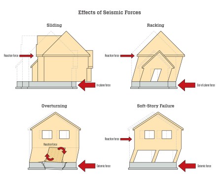
In an earthquake, the ground accelerates horizontally, both back-and-forth and side-to-side. When the force is parallel to a wall (in-plane loading), it can cause that wall to slide off its foundation. When applied perpendicular to the same wall (out-of-plane loading), it causes the top to drift, in turn causing the meeting walls to rack. Partial resistance by building elements to these forces can transfer the horizontal force into rotational forces that can topple walls, pull-out hold-downs, and destroy unreinforced masonry. Large openings in a lower story with a large gravity load overhead are especially vulnerable to racking and collapse.
New Construction
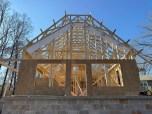
In seismic zones, almost all new construction must be built according to an engineer’s plan. Details in plans will vary, but they almost all share some basic elements.
Reinforced foundations. Foundations primarily support gravity loads, but in a seismic zone, they are called on to resist significant horizontal loads, as well as greater uplift on anchors that prevent shear walls from racking and overturning. This resistance is accomplished with thicker and wider footings, deeper turned-down slab edges, thicker walls and slabs, and much more and larger reinforcing steel. Common details are vertical rebar tying the footing to the stem walls at close intervals and extended rebar hooks overlapping horizontal rebar at corners and height transitions. (For more, see “A Practical Guide to Building in Seismic Zones” by Tim Uhler, Aug/16)
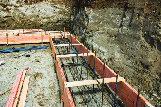
Seismic-resistant new-construction details may vary according to engineered plans, but most wood-frame buildings include these elements: wider, thicker footings with closely spaced rebar verticals, …
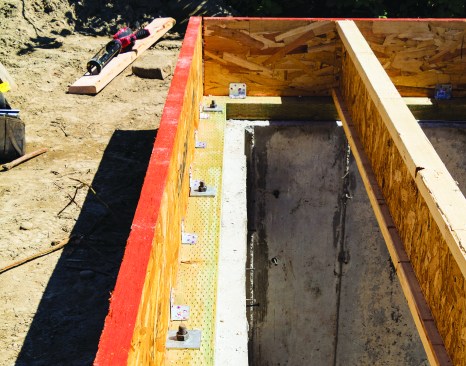
… larger sill anchors and ties to connect the sill and floor framing, …
… reinforcing around wide openings like garage doors, …
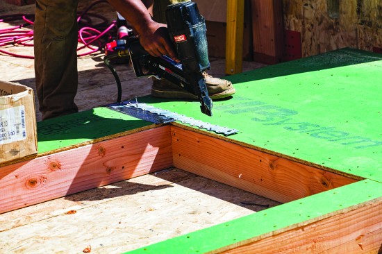
… and strap ties or other connections to complete the load path between floors. (Please note: In the photo above, the author is using a positive-placement nailer to align nails in the strap-tie holes. Don't do this with an ordinary air nailer.)
Slab-on-grade foundations often fare better than stem-wall foundations, owing to the continuous support under interior walls. If stiff enough, interior walls can provide bracing to an overall structure, so many buildings in seismic zones include intentional interior braced walls. To stiffen these walls, slabs usually require a thickened footing running under them. And in stem-wall and basement foundations, beams must be added to stiffen interior braced walls, even though these walls do not support gravity loads. Cripple, or “pony,” walls that are part of a stem-wall foundation can create a short soft story; these are generally limited to 4 feet in height and require full shear panels.
Shear walls. Shear walls are designed to resist the lateral loading caused by ground movement in an earthquake and transfer those loads to the foundation. Engineering plans typically include a shear-wall schedule calling for 15/32-inch CDX (plywood) or 7/16‑inch “APA Rated Sheathing” (OSB). All panel edges that don’t fall on plates must be blocked between studs to accept edge nailing (see “Typical Shear Wall Details,” above). The shear-wall schedule also calls out the attachment of sheathing to framing and the attachment of the wall to the foundation and roof. It’s critically important that panels are gapped 1/8 inch at joints to allow panels to expand and contract without buckling. Longer panels (9 and 10 feet) are often preferred, as they require less blocking in the walls and a lot less edge nailing.
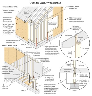
In seismic zones, most engineered plans require exterior walls, and often some interior walls, to be framed as shear walls. This is not just continuous sheathing. True shear wall also requires continuous foundation support; hold-downs to tie posts in shear-wall sections to the foundation; and all panel edges secured with tight nailing and supported by blocking or framing. (Illustration updated from "Shear Walls, The Basics" by Tim Uhler, May/20.)
For shear panel to be fastened correctly, it must be nailed off at the correct spacing and the nails set properly. The shear-wall schedule provided by a designer or engineer typically includes nail size and spacing. It will specify both edge nailing and field nailing.
All shear walls must be mechanically attached to the foundation. The plans usually specify metal straps, hold-downs, closely spaced anchor bolts, or some combination.
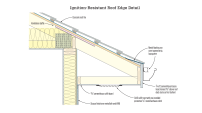
Force collectors. The lateral forces from earthquakes (or high winds) are spread out over the entire area of the floor and roof diaphragms, which in many contemporary home designs is a much greater area than shear-wall areas. Many structural designs will therefore require force collectors (sometimes called “drag struts” or “drag ties”) that gather lateral forces spread through a diaphragm and transfer, or “drag,” them to the shear wall. (For more information, see “Lateral-Force Collectors for Seismic and Wind-Resistant Framing” by Thor Matteson, Oct/03)
Often, much of this work is done by nailing off the roof sheathing, which transfers force to the eaves blocking and from there into the double top wall plate. In seismic zones, frieze blocking is often secured to the top plate with clips or structural screws to ensure the force is transferred to shear walls. In some seismic designs, blocking or bracing, often reinforced with strap ties, may be added in the midspans of roof and floor members to further collect and transfer lateral loads.
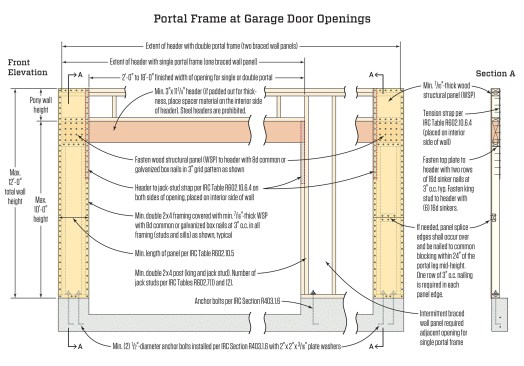
This type of portal frame can be used if the supporting walls are 8 feet tall and at least 24 inches wide (wider for taller walls), and must be bolted to concrete. Other types of wood portal frames are possible (see JLC's “The Portal Frame Option”).
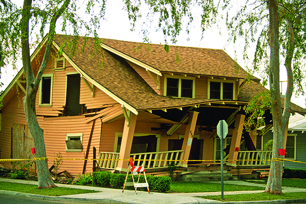
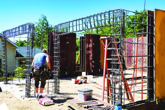
Moment frames. When a lateral force is applied at the top plate of an unsheathed wall, and the wall racks, the studs rotate with respect to the top plate. Shear panels resist this rotation and transfer that force to the foundation. But in a wall with a large opening, such as a garage door or large window wall without enough sheathing area, the opening requires a “moment frame.” In some cases, this can be built with plywood as a “portal frame” if the supporting walls are wide enough (see illustration above), but often it requires steel (see illustration, below). In many garages, the rear wall must be detailed as an interior shear wall to add sufficient resistance to racking. Existing homes built above a garage, or other “soft story” often need to be retrofit with a moment frame (see “Retrofit Moment Frames” by David Lopp, Apr/16).
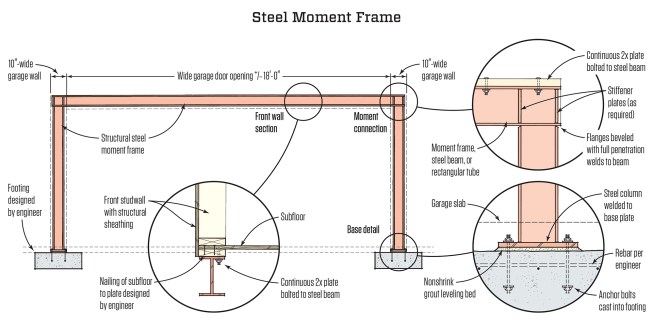
A moment frame can be used to provide shear strength for narrow-walled structures when standard framing solutions are inadequate. In all cases, beam and column sizes and connection details need to be designed by a structural engineer. (Illustration updated 2022)
Seismic Retrofit
Older homes built in seismic zones are often at risk of failure and need to be retrofit to improve stiffness. In many West Coast houses, cripple walls and poor foundation connections are the weakest structural links and (in addition to retrofit moment frames) are the most common fixes to increase a home’s chance of surviving an earthquake. Most of these homes would benefit from stiffening the upper walls and connections as well, but the cost of those repairs is often prohibitive.
The goal of below-floor retrofitting is to connect a house firmly to the foundation and stiffen cripple walls by turning all or part of them into shear walls so that lateral forces are transferred through them into the foundation. In addition to turning cripple walls into shear walls, most of the focus is on strengthening the floor-to-wall connection to transfer lateral loads to the shear walls, and the sill-to-foundation connections to resist sliding. Overturning is often not an issue with cripple walls because the walls are typically relatively short. Therefore, hold-downs to resist uplift at the ends of shear-wall sections are not often called for.
This work assumes the foundation is adequate to hold anchors, which in some older homes it isn’t. The shear strength of the concrete is not the issue. Even unreinforced, 1,500‑psi concrete will be sufficient against shear (the wood members anchored to it are often weaker), but the old concrete may be too weak or too shallow to hold anchors. In these cases, it may be necessary to pour new footings. But usually, this new concrete can be poured around the old.
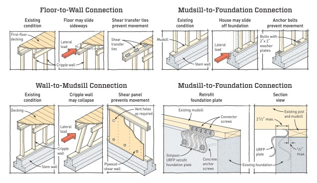
A house with cripple walls must be reinforced at three common weak spots below the floor: The floor must be tied to the cripple walls, the cripple walls must be stiffened with plywood and tied to the mudsill, and the mudsill must be bolted to the foundation. When access is tight and anchors can’t be drilled in from above the plate, Simpson Strong-Tie URFP plates can be used for making the mudsill-to-foundation connection. (Illustration updated from JLC's "Seismic Retrofit for Cripple Walls")
Photos by Tim Uhler; illustrations by Tim Healey