My family and I attend bethel Baptist Church in Prospect, N.Y. When the church was organized in 1976, the founding members had a 24-by-48-foot double-wide mobile home installed to provide a parsonage for the church’s pastor and his family. That mobile home underwent many alterations, repairs, and “mishaps.”
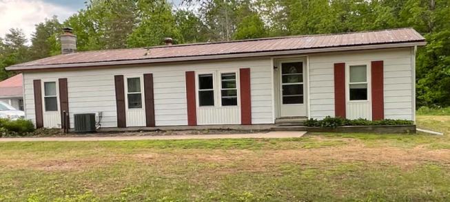
Before: The 45-year-old double-wide mobile home had undergone several alterations and additions, eventually reaching a condition where major repairs were required.
After 45 years, it had reached a condition where routine problems gave way to major ones, including water leakage, mold, and high energy costs, on top of pending structural issues. The one feature of the parsonage that aged without problems was a full basement constructed with 12 courses of concrete blocks and a smooth, flat concrete floor.
After investigating several options for dealing with the building’s deterioration, the membership approved a proposal to remove everything above the foundation and reconstruct a new home on that foundation. I took on the role of designer and construction manager. The task before me was to design a new structure that could be built quickly on a limited budget, reuse much of the existing foundation, minimize future maintenance, be energy efficient, and provide year-round comfort for a family of six. This project is presented here as a case study for building a high-performance home on a reasonable budget.
Structure and Enclosure
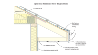
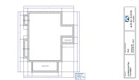
The original 24×48 basement and a later 24×24 addition are outlined in grey in the floor plan below. We cut a Bilco entryway into the existing basement wall and added two small slab-on-grade “appendices” (outlined in orange)—one to extend the width of the main foundation out to 32 feet, and the other to support a small entry vestibule. Both appendices were constructed using a shallow frost-protected foundation system, as shown in the illustration and photos below.
Click here to enlarge image below.
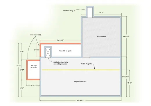
The parsonage floor plan shows the original and new footprints for the building.
The bottom of the footings are 24 inches below finish grade, and 2-inch-thick extruded polystyrene insulation extends outward from the top of the footings to act as a frost barrier.
Click here to enlarge image below.
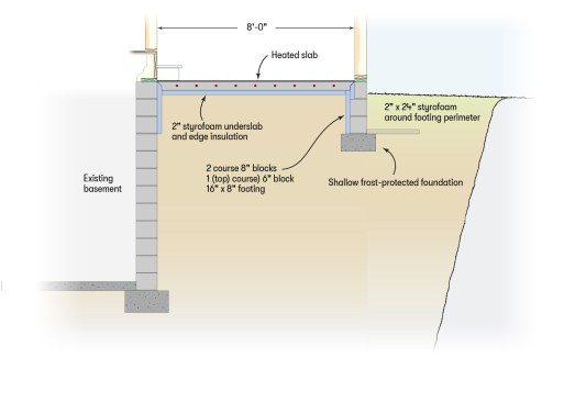
The new foundation areas are protected from frost damage by a shallow foundation with rigid foam around the footing perimeter.
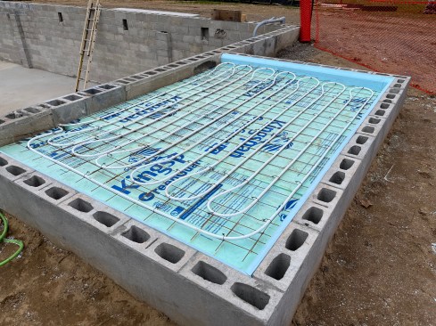
After the stem walls were constructed, we filled the enclosed area with granular soil, compacted it, and covered it with a 6-mil poly vapor barrier and 2 inches of extruded polystyrene. Tubing for floor heating was fastened to the 6×6 WWF (welded wire fabric) reinforcement, and a 4-inch concrete slab was poured flush with the top of the stem walls.
Thermal envelope. We considered insulating the inside of the basement walls but eventually dismissed the idea because of the estimated cost and the possibility of the block walls becoming much colder than they had in the past, which could lead to frost damage. To meet code requirements, 6-inch mineral-wool batts were installed between the 2×12 floor joists. Reinforced nylon strapping holds the batts in place, while roofing nails attach the 2-inch-wide strapping to the bottom of the joists every 24 inches.
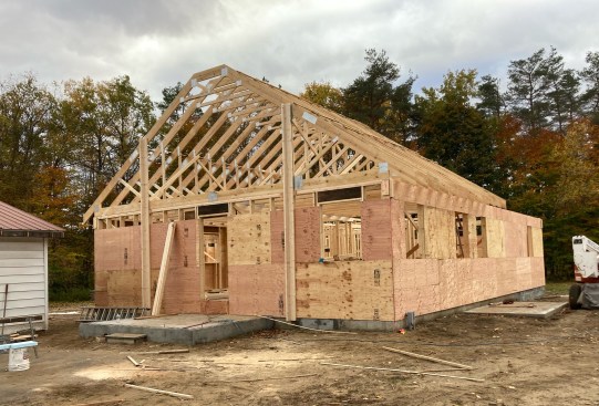
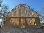
Fast framing: The walls were framed 24 inches on-center. Along with the raised-heel attic trusses, this framing strategy enabled fast construction.
Framing. The 24-inch in-line framing we used for the floor deck and walls reduced the quantity of materials needed and sped up construction without sacrificing strength. Raised-heel attic trusses with 8/12 pitches and 24-inch overhangs were installed directly in line with wall framing. The trusses provided a 16-foot-wide Cape-style upper-floor space that would eventually become two bedrooms and a full bathroom.
All exterior framed walls were insulated with 4 inches (R-28) of spray polyurethane foam. The cavities between the upper cords of the attic trusses were insulated with 7 inches (R-49) of spray polyurethane foam directly against the roof sheathing. This allowed ducting to run through the unfinished space in the trusses and remain within the thermal envelope.
Keeping It Warm
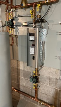
We planned for the project’s HVAC system to be all-electric. A SpacePak iLAHP air-to-water heat pump with a nominal 4-ton (48,000 Btu/hr) heating capacity is the primary heat source, and a 9-kilowatt (30,700 Btu/hr) Electro Industries electric boiler provides supplemental and backup heating.
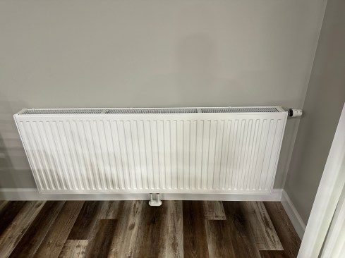
The heat pump maintains the water temperature between 100°F and 110°F within a Thermo 2000 TurboMax reverse indirect water heater tank. This tank—described later—also serves as a buffer tank for a highly zoned hydronic distribution system consisting of 10 Myson T6 panel radiators and two small areas of floor slab heating.
The panel radiators and two floor heating circuits are each equipped with a thermostatic radiator valve that allows heat output to be individually adjusted. These non-electric valves automatically regulate heat output by adjusting the flow rate through each heat emitter. In effect, the system has 12 independently controlled heating zones. In this setup, each heat emitter can compensate for individual preferences or internal heat gains from sunlight, people, or other sources.
Click to enlarge image below.
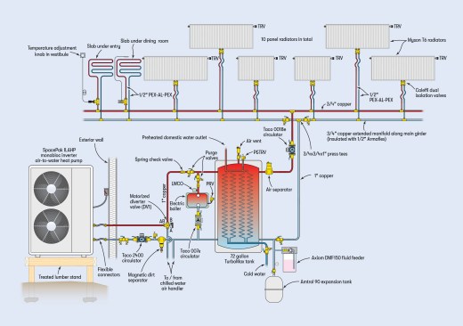
Dual-electric system: Heat pump and small electric boiler piped in parallel to serve tank.
The diagram above and one of the photos in the slideshow below show the panel radiators. The knob of the thermostatic radiator valve is at the upper right corner of the radiator, and the 1/2-inch PEX-AL-PEX supply and return tubes are at the bottom center. The two floor heating circuits use a thermostatic valve body connected to a wall-mounted setting dial via a capillary tube.
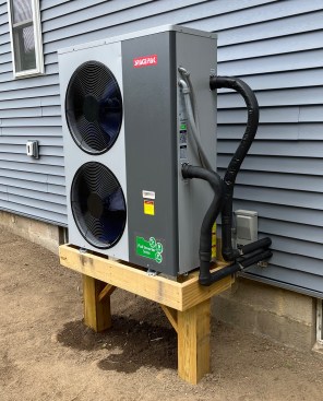
A SpacePak iLAHP cold climate air-to-water heat pump is the home…
We sized the panel radiators and floor heating circuits to provide design-load heat output when supplied with water at 120°F. However, operating experience with the system has shown that it can meet design load using an average supply-water temperature of 105°F. At this low water temperature, the heat pump operates at higher coefficients of performance (COPs).
The air-to-water heat pump is piped in parallel with the electric boiler. Either one can serve as the system’s sole heat source, or both can operate simultaneously if the water temperature in the TurboMax tank drops 5°F below its normal cycling range. The heat pump and boiler are turned on and off using a Tekmar 152 two-stage temperature setpoint controller that continually monitors the tank temperature. This controller prioritizes the heat pump as the “lead” heat source.
The entire hydronic system operates with a 30% solution of ChemFrost inhibited propylene glycol antifreeze. Antifreeze is required to protect the heat pump from freezing. It also protects the entire system from freezing during a prolonged power outage and costs less than installing a properly sized heat exchanger between the heat pump and the rest of the system. And the COP of the heat pump is higher when there’s no heat exchanger between it and the remainder of the system.
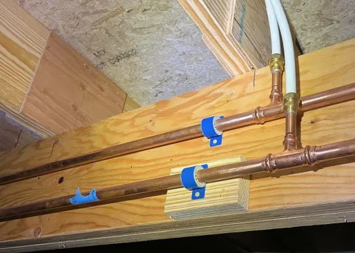
The distribution piping is a variation on “home run” piping, in which a set of ½-inch PEX or PEX-AL-PEX tubes are routed to each heat emitter from a common manifold station. The 1-inch copper piping from the TurboMax tank connects to ¾-inch copper headers that run in opposite directions along the home’s main LVL center girder. The ½-inch PEX-AL-PEX tubing tees into the ¾-inch headers, as shown in the fifth image in the slideshow, above. These headers take the place of a traditional manifold station. With 12 heat emitters widely spread out in the building, this approach saved several hundred feet of ½-inch tubing and many holes that would otherwise be required through floor joists if all the home-run circuits were routed back to a manifold station.
After pressure testing was done, we insulated all the copper tubing as required by code in an unconditioned basement. For this, we used pre-slit ArmaCell elastomeric foam insulation with a ½-inch wall thickness.
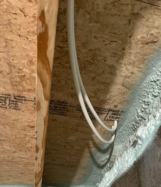
We routed the ½-inch PEX-AL-PEX tubing above the floor insulation and, as such, it did not require insulation. We fastened it to the joists using Genova CPVC C-clips.
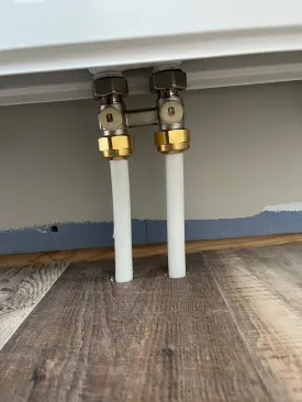
The tubes rise through the subfloor, 2 inches on-center and directly under the centerline of each radiator. They connect to dual isolation valves, as shown in the photos in the slideshow above. These valves allow each radiator to be isolated from the remainder of the system and even disconnected if ever necessary. A split escutcheon plate snaps in place over the piping penetrations.
A single, high-efficiency Taco 0018e circulator handles flow through the entire heating distribution system. This circulator automatically varies its speed to maintain constant differential pressure as the thermostatic radiator valves regulate flow. It comes equipped with Bluetooth communication, allowing its input power, flow rate, and differential pressure to be monitored on a smartphone. At full speed, it draws 44 watts. Under typical system operation, input power ranges between 20 and 30 watts. This circulator can operate 24/7 on approximately $0.13 worth of electricity per day at current local rates. With such a low energy consumption, there’s no reason to turn the circulator on and off during the heating season.
Domestic Duty
The partial schematic below shows how domestic water is heated. The TurboMax tank has several internal copper coils through which cold domestic water passes whenever hot water is drawn at a fixture.
Click to enlarge image below.
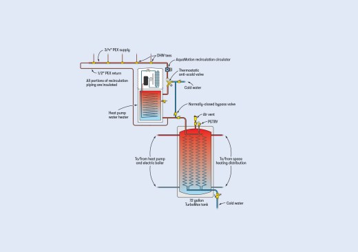
Domestic water is preheated as it passes through copper coils within the TurboMax tank before passing through an existing heat pump water heater. A recirculating distribution system ensures immediate hot water delivery at each fixture.
In this system, these coils can preheat cold domestic water to about 95°F or 100°F. Water exiting the coils passes into a heat pump water heater that had been installed in the original parsonage. That unit boosts the preheated water to 120°F. An insulated DHW recirculation system provides immediate hot-water delivery to any fixture in the home. This arrangement allows the air-to-water heat pump to provide the majority of the water’s temperature lift at a relatively high coefficient of performance (COP), especially during warm weather. The heat pump water heater keeps the basement cool and dry during summer and provides a DHW backup to the main heat pump, if ever necessary.
Keeping It Cool
The air-to-water heat pump also supplies chilled water for cooling. That water is delivered to a hydronic air handler located within conditioned space between attic trusses. The diagram below shows the cooling portion of the system.
Click to enlarge image below.
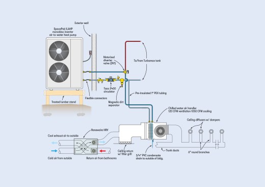
Chilled water from the heat pump is routed to an air handler for cooling. Fresh air from the HRV is injected into the air handler’s return plenum. The airflow provided by the air handler changes between ventilation-only mode and cooling mode.
In cooling mode, a motorized diverter valve directs flow from the heat pump to the coil in the air handler. The heat pump adjusts its compressor speed to maintain a supply temperature of 50°F to the coil.
It’s critically important that all piping and components conveying chilled water are insulated and vapor-sealed. We used pre-insulated 1-inch barrier PEX tubing from Uponor to carry chilled water from the mechanical room to the air handler. It installs quickly and can be connected to rigid piping using cold expansion fittings.
For insulating copper tubing, elastomeric foam insulation such as ArmaCell’s Armaflex is ideal. It comes pre-slit to fit over the piping and includes pressure-sensitive tape to bond the longitudinal seams. All butt joints should be glued with rubber contact cement. We wrapped odd-shaped components, like circulator volutes and air separators, with elastomeric foam tape. The goal is to prevent any contact between chilled surfaces and surrounding air.
During a humid summer day, several gallons of condensate will form on the air handler’s coil and fall into its drip pan. We used ¾-inch PVC piping along with a trap to carry this condensate outside the building. Since we installed the air handler above a finished ceiling, we also installed a secondary drain pan to capture any potential long-term leakage from the air handler’s drip pan.
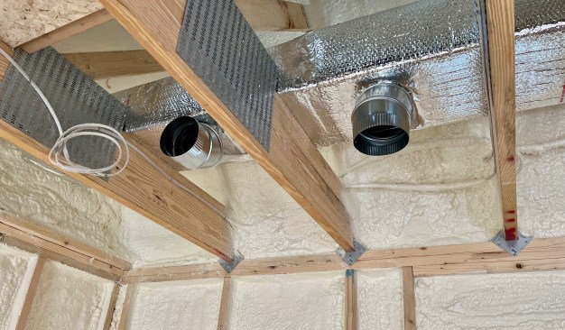
Trunk ducts insulated with bubble foil wrap to prevent condensation transition to 6-inch round branch ducts routed through the spaces between lower truss cords.
Rectangular trunk ducting from the air handler runs along the top of the lower truss cords. Multiple 6-inch round galvanized branch ducts connect to the trunk and run out through the spaces between the 2×10 bottom truss cords. They transition to ceiling diffusers with adjustable dampers; the elbows making the transition are shown in the photo at left. All air delivery is from the ceiling on the main floor and low wall registers in the spaces formed by the attic trusses.
All air supplied through the ducting system returns to a single filter grille located on the hallway ceiling and almost directly under the air handler. When interior doors are closed, return air passes through grilles (made by Tamarack Technologies) that we installed into the bottom of the interior doors (see photo, below). These grilles attenuate light and sound transmission while greatly reducing room air pressurization. This allows for balanced airflow without the complication and cost of dedicated return air ducting.
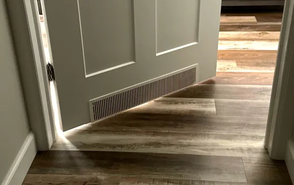
Return air grilles in bedroom doors allow return airflow from all rooms while attenuating sound and light transmission.
A RenewAire heat recovery ventilator (HRV) interfaces to the return side of the air handler. When only ventilation airflow is required, the air handler is wired to run at approximately 120 cfm to match the airflow rate through the HRV. When the system operates in cooling mode, the air handler increases airflow to 1,050 cfm. The HRV draws return air from each of the three bathrooms.
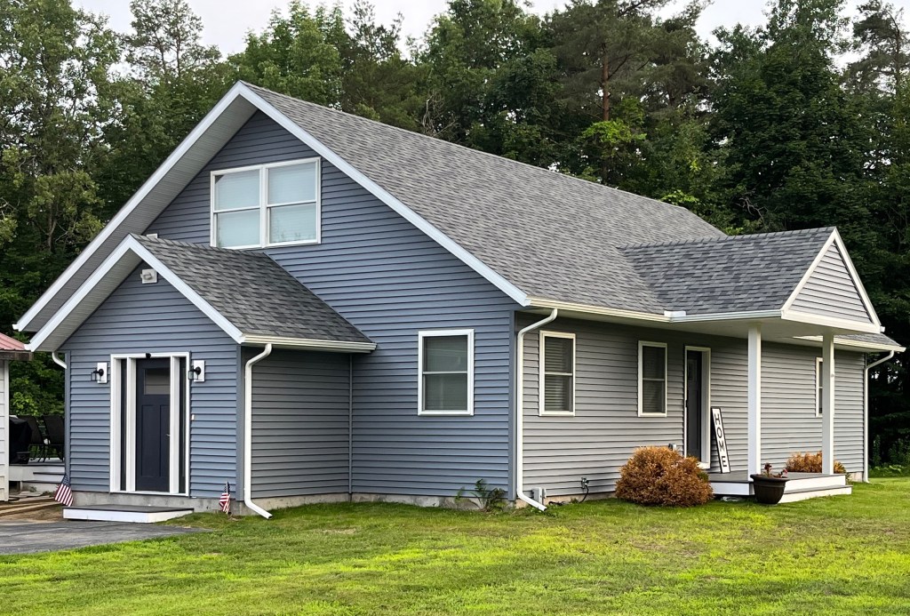
The completed build has five bedrooms and three full baths. Like any project, it had its challenges, but with God’s help this home will serve the church for decades to come.
Photos by John Siegenthaler; illustrations by Ola Kwiatkowska.