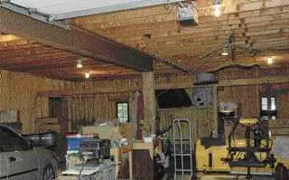
When my client described how he wanted to convert his home’s existing two-car garage into a spacious new living room, I knew it would be a great project for my design/build firm. Measuring 34 feet deep by 28 feet wide, the garage space was a blank slate — little more than an unheated box with a concrete slab for a floor. The garage had a full-height attic that he was planning to convert into a master suite, and the first floor had plenty of space for a nice living room and his many collectibles. The only problem was that the wide-open floor plan he wanted wouldn’t be possible until we figured out a way to support the second floor’s main girder, which was propped up by a steel I-beam running down the center of the garage.

The author replaced the existing steel I-beam and supporting column with a framework of custom-fabricated decorative steel.

When we started the design process — specifically, figuring out how to create a unique space and support the second floor without posts or columns — I immediately thought of local steel fabricator and sculptor John Rubino, whose decorative steel beams are on display in various residential and commercial structures in northern Vermont. Although these structural elements function much like ordinary structural red iron, the stylized beams look anything but ordinary.
With the client’s go-ahead, John and I worked out a plan: We would support the top half of the building without intermediate posts and simultaneously create a living space using exposed steel framing that would become an integral part of the overall design. While John spent about a month fabricating the steel in his Morrisville, Vt., shop (see “Fabricating a Custom steel Beam“), my crew and I readied the building for its new structural elements.
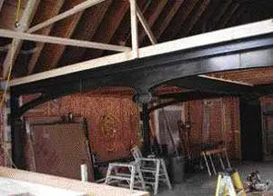
The steel design was relatively simple — two upside-down U-shaped frames connected to another beam running perpendicular to them at the center. Designed with a graceful sweeping curve, the connecting beam would replace the garage’s existing center I- beam and eliminate the need for supporting columns; it would also add a sculptural element to the space.
Getting to Work
Before delivery of the steel, we built a pair of 2×4 walls that would temporarily support the second floor while we removed the existing steel I-beam and posts. Even though we had to frame new openings for a 6-foot patio door and several windows, we purposely left the existing garage-door openings in place to make it easier to bring the steel inside.
About a month after finalizing the plan, John backed his delivery truck into the garage and we lifted the beams off with a chain hoist. John had welded on lifting points near the center span of each beam, to help keep the components nice and level as they went up. This was good thinking, because this steel was meant to be exposed and had been spray-painted and finished with a water-based clear finish called Safecoat Acrylacq (AFM, 619/239-0321, www.afmsafecoat.com). This coating is pretty tough, but we still had to handle the steel with care so as not to scratch it. The lifting points made the process a lot easier and safer.


Also, like any good fabricator, John called me ahead of time to confirm that the steel loops wouldn’t hit a joist or interfere with pipes or ductwork.
We lowered the 1,400-pound beams onto four-wheel dollies and, after a little jockeying, rolled the first one directly below where it would be installed. With most of their weight up top, the arched girders had to be balanced carefully, so we were extremely careful while we moved them; we swept the floor thoroughly beforehand to make sure the casters wouldn’t get hung up on small stones or wood chips.
Before raising the first of the two steel arches, we had to deal with the existing three-ply wood girder running perpendicular overhead. Because the girder would otherwise prevent us from raising the beams all the way into position, we notched it with a reciprocating saw for the necessary clearance, then reinforced it with a specially fabricated saddle-type hanger that supported both sides of the notched wooden girder and left room for the new supporting steel beam to slip in from underneath.


Making Connections
Once we had the hanger in place, we ran the chain hoist through a hole in the floor above and slowly lifted the beam. When it was in position, we slid in the matching steel columns on both ends. It’s important when working with structural steel members to start all the bolts before tightening any of them. Leaving them loose gives you a little wiggle room for lining up the other bolts, while a tapered drift pin makes aligning the holes in the heavy members much easier.


It’s also important to use the right fasteners. The A325 5/8-inch bolts we used are designed for structural steel applications. They’re equal in strength to a normal grade-5 bolt, but have larger heads than the ones you’ll find at the hardware store; John gets them from Fastenal (507/454-5374, www.fastenal.com). The larger head spreads the load and matches the visual scale of the large steel members.
After tightening the bolts connecting the beam and supporting columns, we fastened temporary blocking to the framing to hold the frame in position. Then we raised the second frame and installed its posts the same way. Finally, we moved the chain hoist to the center of the room to install the connecting girder that would support the floor system.
Securing the Posts
With all the pieces in place and the bolts tightened, we went about securing the post bases to the floor. Rather than cut the existing slab for new footings, our engineer specified 1-foot-square post bases so they could rest on the existing 4-inch-thick slab. Since it would have been impossible to slide the posts under the beam with anchor bolts sticking out of our post footings, we used wedge anchors to fasten the post bases to the concrete floor.
With a rotary hammer and a 5/8-inch bit, we drilled through the base into the concrete, blew out the holes with compressed air, and drove in the anchors. Steel shims compensated for the less-than-perfect floor. Once the posts were secured to the floor, we lag-screwed the posts through the wall into blocking that we had installed earlier.


From this point on, construction was fairly conventional. We framed a pair of large window openings to replace the garage doors and reinforced the wall against wind with some exposed structural timbers designed by an engineer. We poured an additional slab over the existing one for a radiant heating system and added a master suite upstairs, complete with a large bedroom and three-quarter bath, with access via a curved wooden staircase.
The steel frame in this project cost about the same as high-end timber-frame components. Although conventional red iron would have been cheaper, we would have had to disguise the members with wood or bury them in the structure, which would have added to the price. With this design, the steel performs its structural task while adding a decorative element to the new room.
Bob Petrichkois a design/builder in Stowe, Vt.
Fabricating a Custom Steel Beam
by John Rubino Though many home builders and remodelers don’t realize it, structural steel is actually easy to work with. True, you can’t cut it and nail it like wood — but with a little planning and prefabrication, incorporating steel beams into residential projects is a fairly simple process. And the beams are typically lighter and cost less than their engineered-lumber equivalents.
Sizing a steel girder is not much different than sizing a wood beam. I start with the loads and the loading conditions, then consult the Manual of Steel Construction: Allowable Stress Design (published by the American Institute of Steel Construction) for a beam that will work. As with wood, a deeper beam of a given thickness will carry a greater load than a shallower one.
The project shown in this article involved two sculpted-steel moment frames supporting a center floor-carrying beam between them. The beam itself, which carries uniformly distributed floor loads, was easy to size using tables contained in the steel manual. Where the center beam hits each moment frame, there’s a point load, which is a little trickier to design for — but again, all of that is covered in the steel manual.
I figured the point load at the center of the 28-foot span to be 9,450 pounds. Consulting the manual, I found that a W14x26 beam would handle the load with a large safety margin built in, so I used this beam’s dimensions — 137/8 inches tall by 5 inches wide — as a starting point for my design.
I do my custom beam design work on the computer in IronCAD, a design software used by engineers of large industrial projects. It allows me to spin the piece around in three dimensions and create 3-D walk-throughs to help customers envision the final product. Plus, it lets me calculate the physical properties of the piece. In this case, I determined that the beams would weigh 1,617 pounds per span, including the columns, and that their total surface area was about 36,000 square inches, which is helpful information to have when calculating coating quantities.
Once the design was completed, I printed out the drawings and sent them off to Ina Hladky, a consulting structural engineer in Essex Junction, Vt. After a few minor changes, she approved the design, and I was ready to begin fabrication.

I cut the web sections on a 36-inch band saw, then welded the preformed flanges onto the edges. Before I start cutting, I print full-size patterns on a HP DesignJet 488ca plotter and tape the pattern to the steel. Since I’m often cutting long pieces that require me to stand 10 feet or more from the saw, I have a closed-circuit TV camera mounted above the saw so I can watch the blade on the monitor.

I form the flanges with two machines that I designed and custom-built for the purpose. For larger sweeping bends, I roll the steel through the “RubiRoll.” With 30 tons of available hydraulic pressure, this unit allows me to form material up to about 6 inches wide by 3/4 inch thick or 10 inches wide by 5/8 inch thick. For tighter bends, I use the “RubiRam,” which I lovingly call my log-splitter on steroids. With its 62 tons of hydraulic capacity, I can bend material up to 10 inches wide by 3/4 inch thick.

Once the flanges and webs are ready, I assemble the pieces with a wire-feed (or MIG) welder and ESAB brand wire — dual-shield 7100 Ultra .045, a flux-cored wire. The process uses a gas shield of 25 percent argon and 75 percent CO2, which gives me the best combination of strength and appearance.
After welding, it’s on to finishing. Because I don’t like to see any grinding marks, I weld very carefully, which allows me to use what I call “honest finishes” — clear coatings that don’t cover up welds, blemishes, and fabrication marks.
John Rubinois a steel fabricator in Morrisville, Vt. For more examples of his work, visit www.rubinosculpture.com


