Victorian homes, with all their steeply pitched roofs, angles, and gingerbread (corbels, brackets, scallops, and so forth), are a challenge for the carpenter to trim and a bigger challenge for the homeowner to maintain. Queen Anne homes, a specific Victorian style, are also all about radiuses — radius porches and verandas, radius windows, radius gable-end decorations, and radius turrets. In this article, I’ll describe how we tackled the radius balustrade work for a contemporary Queen Anne we’ve been working on recently.
New-Tech Materials
When we met the architects on this project, Brian Lehrman and Marlene Ayer from Artistic Residential Creations, they told us that the owners loved the Victorian style but hated maintenance — a tough contradiction for a finish contractor to sand flush. To satisfy on both fronts, we used the latest generation of materials available for exterior trim work, products that won’t warp, twist, cup, crack, or peel within two years, something impossible with even the best second-growth redwood.
For the molded radius pieces — all the balustrade railings — and any decorative turned elements, we used high-density rigid polyurethane moldings from Fypon (800/537-5349, www.Fypon.com). For all the flat trim, including the radius spindle railings, we used treated exterior composite trim from Miratec (800/255-0785, www.miratectrim.com). While I was comfortable with my knowledge of polyurethane moldings and confident that Fypon would outlast wooden railings and balusters, I had reservations about exterior composite trim. To quell my fears, I cut a 4-inch-square piece of the 1-inch trim, left the ends raw, and submerged it in a bucket of water under a piece of lead for two weeks. When I removed the material, it was still exactly the same size and the water hadn’t penetrated the raw ends: Shaving less than 1/16 inch off the raw ends revealed clean, dry trim. After that test, and after reading all the literature I could find on installing composite trim and polyurethane molding, I was ready to start work on the job.
Spindle Railing
Our installation began with the spindle railing — the short decorative balustrade that hangs from a Victorian porch beam — because we couldn’t install the balustrade below until the decking was finished. The top and bottom rails on the straight spindle runs were easy: We used 3-inch-wide material, ripping the top rail to 2 inches and the bottom rail to 2 1/2 inches, then beaded the bottom rail with a roundover bit so water would roll off. To make sure the spindles were spaced evenly, I used a Construction Master Pro calculator (see “Speedy Layout With a Calculator”).
For the radius sections of railing that ran around the turrets, we ordered 4/4 x 12- and 5/4 x 12-inch Miratec boards. I first used the calculator to determine whether I’d be able to get every rail out of a single 11 1/2-inch-wide board — I didn’t want to laminate any of the bottom rails because they’d be spanning almost 9 feet. I’m no math whiz, but it didn’t take me long to figure it out: I punched in the 9-foot span and hit RUN, then entered the 12-foot radius (you have to push the CONV key first, then the DIAG key). Finally, I hit RISE, and the result — 10 1/2 inches — landed well within the width of my 11 1/2-inch boards.
Cutting the Radius Rails
I used an inexpensive site-built trammel arm and plunge router to cut the radius rails. I screwed the railing material down to a sacrificial piece of scrap on top of my workbench. Porter-Cable manufactures a great adjustable fence for its plunge router, which can be easily adapted for standard routers. I reversed the fence, then attached a piece of 1×4 to extend the trammel arm. The radius at the outside rim of the deck was 12 feet (see Figure 1). However, the railing was centered on the porch columns, 6 inches from the edge of the deck, which made the center of the railing an 11-foot-6-inch radius. Since the bottom railing was 2 1/2 inches and the top rail was 2 inches wide, I needed four radius center marks in the trammel arm.
I first marked the radius centers with a pencil, then punched them with my nail set (those holes had to be located perfectly) before attempting to drill pilot holes. I used a drywall screw as a trammel point. After all the setup, swinging the plunge router on the trammel arm was a breeze. I made several passes for each cut, burying the bit about 3/16 inch with each pass. Miratec cuts easily, but taking too deep a bite with the router bit will stress the trammel arm and throw off the smoothness of the cut.
Site-Built Router Jig
Figure 1.A site-built router trammel jig (above) cut the four radii needed — two inside, two outside — for the decorative spindle rail and the main porch railing. A drywall screw (below, top) served as the pivot point, while a Porter-Cable edge guide secured the router (below, bottom).
Extendible Measuring Jig
I knew that measuring the exact length of each railing was going to be a problem and that getting a perfect cut on the end of the rail would be even more difficult. So I cut two extra 3/4 x 2-inch spindle rails for each section, then sandwiched those two pieces to use as a template (Figure 2).
Working in place between the porch columns, we slid the pieces apart until both ends were tight against the posts. We then scribed both ends and trimmed them until the joints were snug. At that point, we screwed the two pieces together securely, then used that template to mark the top and bottom rails for that section.
Figure 2.Two extra pieces of railing served as an extendible template for laying out the radius rails (left). After scribing the ends to fit the posts, the carpenters stretched the two pieces apart until they were tight against the new posts, then fastened the pieces together with drywall screws. Tracing the template directly onto the railings guaranteed a tight fit (right).
Laying Out the Spindles
Laying out the spindles stumped me for a minute while I considered how to use the Construction Master to calculate the spacing around the radius. Then I decided on a much simpler and almost as exacting method. I first laid out the centers of the two end spindles, 2 inches in from each end of the rail. Then I ripped a 1/4-inch-thick strip of 3/4-inch exterior trim, curved it around the radius, and marked the distance between the two end spindles (Figure 3). After that, I was able to use the calculator to find the centers of each spindle. I marked them, then bent the trim strip around the radius again to transfer the center marks onto the rail.
Figure 3.Instead of trying to lay out the spindle centers on the curve, the author used a thin strip of flexible material, marking it in a straight position then bending it to the radius to transfer the marks.
Assembly & Installation
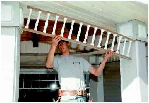
Assembling the rails was definitely the easiest part of the job (Figure 4). First we drilled pilot holes with a tapered countersink so the painters could fill over the decking screws that secured the spindles. Before placing the spindles, we squeezed a good dab of Fypon adhesive on top of each hole. Once all the spindles were installed and the adhesive had dried, each ladderlike section was rigid and strong, even though the spindles themselves are lightweight unreinforced polyurethane.
Installation was almost as easy. Because we had used templates, each section fit perfectly the first time. We secured the top rail to the ceiling with galvanized finish nails, toenailed the bottom rails to the post capitals, then installed brackets beneath the railing with nails and more polyurethane adhesive.
Figure 4. Holes for the galvanized screws were predrilled in both the rail and the spindles (left), but the Fypon adhesive provides the real strength for the spindle assemblies (right).


