Residential decks have become increasingly elaborate to include covered wood-framed structures one or more stories in height. Unfortunately, the model building codes have been slow to adopt comprehensive prescriptive deck construction guidelines, with the 2021 International Residential Code (IRC) continuing to limit such guidelines to decks with a single, uncovered level. However, once you understand and can properly apply the tributary-area approach contained within IRC tables, you can use it to size deck footings and select deck columns or posts for covered and multilevel decks.
Understanding Common Errors
One of the main challenges presented by covered and/or multistory deck design is the vertical and lateral-load development of the free-standing posts. You don’t want to use platform construction with posts installed at each story, because decks don’t have structural wood panels (for example, OSB or plywood) to provide long-term stability, as a typical platform-framed structure would. In addition, the typical nailed connections at post ends are insufficient to resist lateral deck movement and uplift forces.
Vertical loads need to be transferred through the floor framing to the footings, and the beam-to-post connection must be sufficient to resist both lateral and vertical uplift forces, a crucial detail that’s often overlooked in the construction of multilevel or covered decks. In this article, I’ll describe a simplified design and construction approach using continuous posts that will provide lateral stability and ensure a continuous load path from the foundation to the uppermost floor or roof level.
Deck Post Sizing
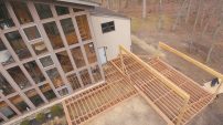
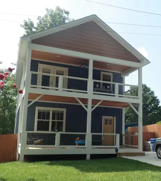
Let’s look at a typical two-story covered deck, as shown below. The roof and floor framing are supported by beams at each level that are connected to the house and three posts across the front. The residential floor live load is 40 pounds per square foot (psf) with a 20-psf roof live load. The deck dimensions are 8 feet by 24 feet with a 1-foot roof overhang, and the maximum vertical distance between the support beams is 9 feet, which is used to determine the post height.
The tributary areas for each level and the roof, including cantilevers and overhangs, must be added together when sizing the deck posts that support the two-story 8-by-24-foot covered porch shown here. These tributary areas are illustrated in the drawing below.
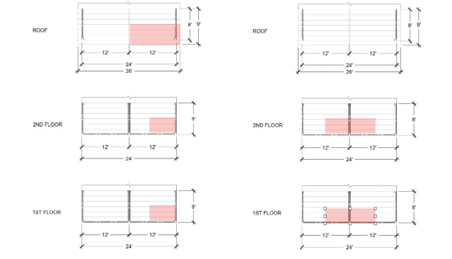
Shaded above, at left, are the tributary areas supported by a corner post of the two-story 8-by-24-foot covered porch shown in the photo (top). The total tributary area supported by each post is 65 sq. ft. (roof) + 24 sq. ft. (second floor) + 24 sq. ft. (first floor) = 113 sq. ft. Similarly, above, at right, the tributary areas supported by the center post are shaded. There are no loads on the center post from the truss roof, while the tributary areas on the first and second floors measure 48 sq. ft. each, for a total tributary area of 96 sq. ft. Tributary areas are used to size the posts and footings.
Tributary area. In the illustrations below the photo, I show the tributary areas at each deck level that are supported by one of the corner posts (at left) and by the center post (at right). When you use the deck post sizing table (Table R507.4) in the 2021 IRC, the tributary areas for each level and the roof, including cantilevers and overhangs, must be added together. On our deck, each corner post supports a tributary area from the truss roof of 65 square feet, which includes the overhangs, and a tributary area of 24 square feet at each floor level. To find the total tributary area supported by each corner post, add the tributary areas for the roof and the two floors: 65 + 24 + 24 = 113 square feet.
Because of the truss roof, the center post supports only the first and second floors. The area on each floor supported by the center post measures 4 feet by 12 feet, so the calculation to find the total tributary area is 48 square feet x 2 = 96 square feet. Because the 113-square-foot tributary area supported by each corner post exceeds the area supported by the center post, I use the corner-post tributary area to size all three posts.
IRC Table R507.4 shows deck post sizes based on load, wood species, tributary area, and maximum post height allowed. For the load, I use the larger of the floor live load or ground snow load. From the table, a southern pine 4×6 post would be sufficient to support a 113-square-foot tributary area with a 40-psf live load or ground snow load for the building location and a deck post height less than 9 feet 8 inches. If a square post is preferred for aesthetic reasons, you could use a 6×6. Remember, a one-piece post ensures the load path is continuous to the footing as required by the code.
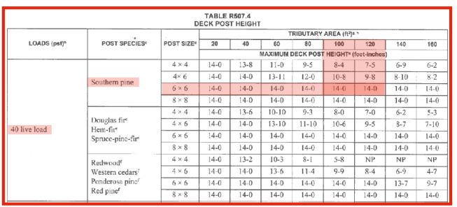
Table R507.4 is copyrighted material excerpted from the 2021International Residential Code. Copyright © 2021. International Code Council, Inc. All rights reserved. Reproduced with permission. www.ICCSAFE.org.
After calculating the tributary area and load, use 2021 IRC Table R507.4 to size posts according to height and wood species. In this example, with a maximum tributary area of 113 square feet and a 40-psf live load, either 4×6 or 6×6 southern pine posts could be used for the porch’s corner and center posts.
In this example, 20-foot 6×6 corner posts are selected and must be continuous from the top of their concrete footings to the second-floor ceiling. The posts are braced by the intersecting beams at the floor and roof level, resulting in unbraced lengths between levels that are less than the 14-foot maximum table value for 6x6s. (For more on sizing deck posts, see “Better Deck Post Sizing” by Glenn Mathewson, JLC/PDB, Mar/22.)
Post footings. The same tributary-area approach used for sizing the deck posts can also be used to size the post footings, this time by referring to 2021 IRC Table R507.3.1. You will need to first identify the soil’s load-bearing capacity to then determine the appropriately sized square or circular footing. (For more on sizing footings, see “Better Deck Piers” by Mike Guertin, PDB, Feb-Mar/15). For soil with a 2,000-psf load-bearing capacity, a live or ground snow load of 40 psf, and a 120-square-foot tributary area, you would use a 21-inch-square or 23-inch-diameter footing that’s 7 inches thick.
Framing. The prescriptive tables in the IRC may be used to select rafters, joists, beams, and decking, but covering those in detail is beyond the scope of this article. However, when you’re sizing the roof framing members, it’s important to know the ultimate design wind speed and the building exposure category.
Similarly, floor joists and beams may be selected from the Exterior Decks section of the code (R507). Size members for the appropriate live or ground snow load shown in the table. You’ll need to calculate the support beam’s load to the post to select the correct manufactured-beam-to-post connector.
Deck Post Connections
The connections are the most critical component of multilevel and covered decks and must be designed to resist gravity, uplift, and lateral loads. Roof beams should be connected to the post based on an uplift load that may be determined from IRC Table R802.11.
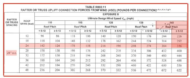
Table R802.11 is copyrighted material excerpted from the 2021International Residential Code. Copyright © 2021. International Code Council, Inc. All rights reserved. Reproduced with permission. www.ICCSAFE.org.
While probably not familiar to most deck builders, 2021 IRC Table R802.11 can be used to determine uplift loads on the deck-post-to-roof-beam connection. As shown in the shaded area, the uplift force for each truss connection is 356 pounds, or 178 pounds per foot along the length of the beam supporting the roof trusses. The total uplift load on the post = 178 x 5 (half the beam span + 1-foot overhang) = 890 pounds.
In our example, the truss roof has a 5:12 slope and 24-foot span, and trusses are spaced 24 inches on-center. The building is located in a 140-mph ultimate-wind-speed zone with an Exposure Category B. According to Table R802.11, the truss-to-beam tie-down connector should be sized to resist 356 pounds. The beam uplift force to the post may be calculated by dividing 356 pounds by the truss spacing (2 feet) to arrive at a load of 178 pounds per foot. The tributary roof length to the post is equal to the 12 inches of the overhang plus half the 8-foot beam span, or 5 feet. The total uplift load to the post end is then 890 pounds (178 pounds x 5 feet). A post cap or notch (with fasteners checked for uplift) as shown in IRC figures R507.5.1(1) and R507.5.1(2) should be used at the topmost post elevation to attach the beam.
Greg DiBernardo
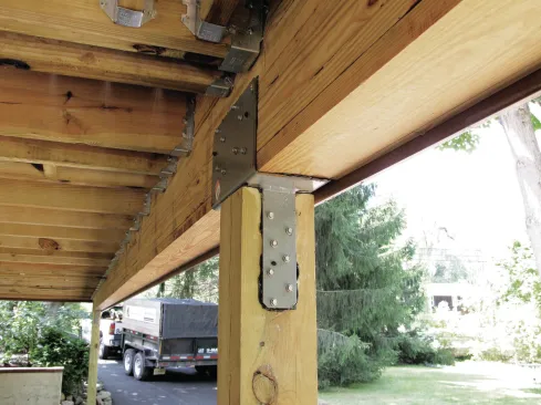
Metal connectors help keep posts and beams aligned at this critical load-path connection but also play an overlooked role in resisting uplift loads. The fasteners should be checked per Figure R507.5.1(2) (shown below) in the 2021 IRC for a covered-deck uplift load.
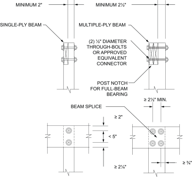
Figure R507.5.1(2) is copyrighted material excerpted from the 2021International Residential Code. Copyright © 2021. International Code Council, Inc. All rights reserved. Reproduced with permission. www.ICCSAFE.org.
Each floor beam should be attached with a manufactured connector to a post that’s continuous through the floor cavity. The load for connector sizing can be calculated by taking the tributary area at each level multiplied by the sum of the floor live load or ground snow load plus 10 psf (in published tables, code assumes the weight of the deck framing members is 10 psf). In our example, the second-floor center beam has a tributary area of 48 square feet (12 feet x 4 feet). The beam load to the center post is 48 x (40 + 10), or 2,400 pounds. Roof gravity loads are determined in the same manner.
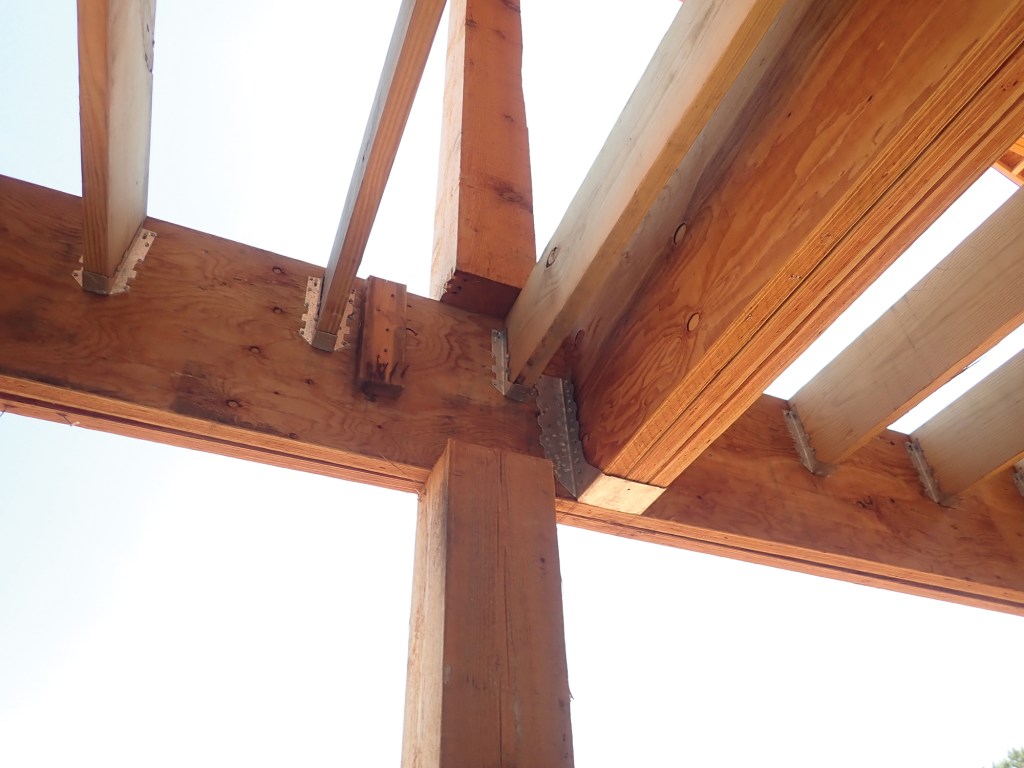
Beams at each level should be connected to the post face with manufactured hardware sized for the calculated beam load to the post (Figure 6). The post needs to be wide enough for the attachment, which—depending on the hardware—may require you to increase the size of the post. Steel hardware should have corrosion protection for the environmental conditions anticipated and meet a minimum of G185.
The post should be connected to the footing with a manufactured connector or embedment into the soil or concrete (see IRC Figure R507.3 for prescriptive post-to-foundation details). When choosing a post-base connector, be sure the manufacturer’s published gravity and uplift values exceed the calculated roof- and/or floor-beam loads to the post. In our example, the roof-beam loads to the post are 2,100 pounds downward (gravity) and 890 pounds uplift. Additionally, floor-beam loads to the post are 1,200 pounds downward at each level. Therefore, the post-base connection should have published capacities that exceed 4,500 pounds downward (2,100 + 1,200 + 1,200) and 890 pounds uplift.
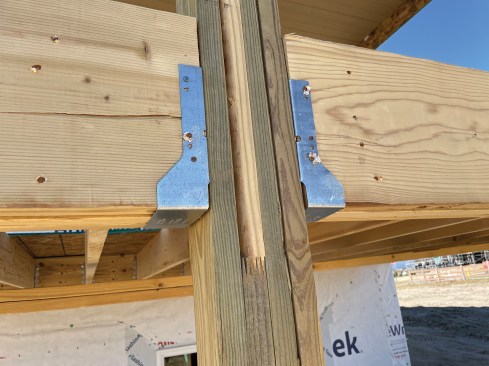
When connecting beams to continuous posts, choose metal hardware sized to fit the posts as well as for the loads. Here, the connectors have inward-turning flanges.
Finally, remember that to resist lateral loads, a multilevel deck or porch will need to be connected to the building with one of the methods shown in IRC R507.9.2. These tension devices (either two devices with a stress design capacity of not less than 1,500 pounds, or four devices with a 750-pound capacity) are required at the roof and each floor level.
While the IRC may be used to design the deck framing members for a multistory or covered porch following this simplified approach, a licensed engineer or architect can help to optimize the members and connectors. Additionally, design professionals can assist in the selection of engineered posts or in the design of built-up posts when lengths exceed what is readily available for solid-sawn posts. ❖
Photos and illustration by Scott Coffman, except where noted