Mike Guertin
When a pier is angled, deck loads are transferred to the pier’…
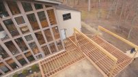
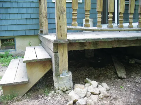
On my last two deck rebuilds, the concrete supporting the existing framing was inadequate, and the decks had suffered for it. The footings were too small and too shallow and the piers were too misshapen, which led to settling and frost heaving that weakened the ledger connections (a safety issue) and to sagging beams that left the deck surfaces wavy. Unfortunately, this situation isn’t unusual, as many deck builders rely on rules-of-thumb to size their footings and piers, then hand off the digging, forming, and pouring tasks to the least skilled laborer on the crew. But a solid foundation is critical for the stability and long-term durability of a deck, so I take the time to make sure my footings and piers are sized and installed properly.
Poured concrete piers aren’t the only foundation option for decks, of course. Other choices include pinned piers, helical piles, or even precast concrete pier blocks with built-in brackets, for those lucky enough to live in areas without frost (see “Footings From New England to California,” Professional Deck Builder, May/June 2007). And even in cold climates like mine, many builders just use PT posts set on (or embedded in) concrete footings at the bottom of the hole. But to prevent decay and problems with anchoring the post to the footing, I prefer to support a deck with continuous columns of concrete that extend from the bottom of the hole to above grade.
Digging deep holes and filling them with concrete is labor-intensive work, though, so I like to do the job as efficiently as possible. In Part 1 of this article, I’ll describe how to design footings that are adequate, but not oversized. In Part 2, I’ll show you how to install them.
Guess, Calculate, or Use a Table?
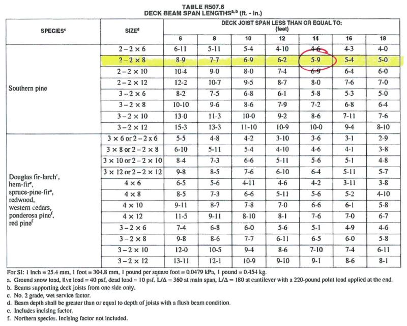
The number of footings needed to support a deck beam is dictated by the beam’s size. Unless the deck requires engineering, I refer to a beam span table as I design the framing. There’s one in DCA6, the American Wood Council’s Wood Deck Construction Guide (awc.org), though I’ve found that the 2015 IRC’s new span table is a bit more generous. Once I’ve determined exactly how many footings I’ll need, I can determine how large each one needs to be.
Footing size. Some deck builders use rules-of-thumb to size footings that may or may not be adequate. Others err on the side of caution and dig unnecessarily oversized footings. A third option for math-averse (but cautious) deck builders is to refer to DCA6’s prescriptive footing sizing table, which supplies footing sizes based on the beam span and joist span. The footing sizes are conservative—the assumed soil bearing capacity is 1,500 pounds per square foot (psf)—and not all beam and joist spans are listed, so often you have to move up to the next larger span. Unless your soils are really poor, you can’t go wrong using the prescriptive method.
I’ve tried all three approaches at different times in my career, but for the last dozen years I’ve calculated the size of each footing during the deck design process. The calculations take only a few minutes and they assure that I’m following best building practice without going overboard. If the soil is dense, with a higher bearing capacity than 1,500 psf, for example, I’ve found that I can greatly reduce the footing size—and save quite a bit of concrete—by determining the tributary load on each footing and assessing the soil’s bearing capacity.
Tributary load. All versions of the International Residential Code (IRC) from 2000 through 2015 call for decks to be designed for a 40-psf live load (which accounts for the owners, their guests, and their furniture and other portable stuff) and a 10-psf dead load (to account for the weight of the deck itself); add the two together for a total load of 50 psf. The weight of snow also comes into play in areas where the snow load is greater than 40 psf; if you’re in one of those areas, substitute the snow load for the live load to determine the total load. There’s no need to add live and snow loads together, since it’s assumed that the owner will shovel off the snow before using the deck. You should also check the live load requirements of your local jurisdiction, which may substitute a greater live load for the 40-psf figure. If a hot tub is planned, total loads can be closer to 100 psf (see “Getting Started With Hot Tubs,” Professional Deck Builder, Jan/Feb 2014).
At 50 psf, the total load on a deck measuring 16 feet deep and 20 feet wide would be 320 sq. ft. x 50 psf, or 16,000 lb. A tributary portion of that load is distributed to the beam (and then to the footings), and a tributary portion to the ledger board, as shown in the drawing. In this example, there are two different-sized tributary deck load sections:
End Sections
9 ft. x 4 ft. 3 in. = 38.25 sq. ft.
Middle sections
9 ft. x 5 ft. 9 in. = 51.75 sq. ft.
To find the total load bearing on each footing, multiply the area of each section by the total load per square foot (50 pounds).
End footings:
38.25 sq. ft. x 50 psf = 1,912.5 lb.
Middle footings:
1.75 sq. ft. x 50 psf = 2,587.5 lb.
What About the Weight of the Footing?
The dead load figure (10 pounds per square foot) in the IRC covers the weight of framing, decking, and railings, but generally doesn’t include the weight of the footings. But should it? Some argue that this weight can be ignored, since the soil removed from the hole is close to the mass of the concrete filling the hole. Others argue that the full weight of each footing should be included in sizing calculations. A third argument is that the net difference between the mass of the concrete and the mass of the soil removed should be added to the tributary load on each footing.
I actually weighed the silty gravel subsoil from a couple of footings and found that it weighed about 110 pounds per cubic foot. Cured concrete weighs about 150 lb./cu. ft. Adding the full weight of a 12-inch-diameter footing tube that has an overall height of 4 feet—which holds about 3 cubic feet of concrete and has a total mass of 450 pounds—to a tributary deck load of 1,912.5 pounds yields a total load of 2,362.5 pounds. Meanwhile, the net difference between the soil and the concrete is 40 lb./cu. ft., so the net difference between the concrete footing mass and mass of soil removed from the hole is 120 pounds. Add the net difference to the tributary load for a total of 2,032.5 pounds (1,912.5 + 120). (Note: The 12-inch-diameter footing is a guess at this point. The actual base of the footing may need to be greater or may be smaller.) In practice, since the actual weight of the framing and decking materials often don’t add up to 10 psf, there’s probably enough prescriptive dead load capacity left to handle the difference in the weight of the concrete and the excavated soil for many decks. —M.G.
Soil Bearing Capacity
You can guess at your soil’s ability to resist those loads—or bearing capacity—by comparing it to the five soil types listed in Table R401.4.1 of the 2012 IRC. They range from 12,000 psf (crystalline bedrock) down to 1,500 psf (for soils composed of a mix of clay, sand, or silt). If you aren’t comfortable grading your soil this way, you can check with the local building department, which may have soil maps that can be used to guide the soil-bearing-capacity determination.
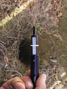
I actually measure soil density using a simple penetrometer, which is much more accurate than basing the soil’s bearing capacity on its type. Often I find that the soil is stronger than the soil type would indicate, and that footing sizes can be reduced significantly. More importantly, I’ve found in some cases that the soil’s bearing capacity was less than what would be expected based on local soil maps or soil types.
There are a variety of penetrometers on the market, from simple pocket versions (like the one I use) that cost as little as $60 to engineering-grade models—called cone penetrometers—with digital readouts, which can cost more than $1,500. To take a reading I dig a footing hole down to virgin soil below frost level, carefully removing loose soil from the bottom of the hole. Without tamping or otherwise disturbing the soil, I press the penetrometer into the earth in five to 10 spots, trying to avoid stones. I record each reading, reject the anomalous ones, and average the similar ones together. Because the scale on the model I have reads in tons, a quick conversion to pounds is needed.
Always check with your local building official before using a penetrometer. He may or may not take your word for the readings you take. I’ve been lucky that most of the officials in communities where I work know my work and trust my readings.
Size the Footings
To find the necessary area of a footing, I divide its tributary load by the soil’s bearing capacity. For convenience, let’s assume a bearing capacity of 1,500 psf. And while it’s probably not necessary, for this example I’ll add in the net mass of the concrete to the total tributary load for each footing (see “What About the Weight of the Footing?,” page 28). To make it easier to translate the result into a square or round footing, I usually convert it from square feet into square inches.
Footing area.The formula I use to calculate footing area is (tributary load + net concrete) ÷ soil bearing capacity. Here, I’ll use 1,500 psf for the soil bearing capacity.
End-footing area
(1,912.5 lb. + 120 lb.) ÷ 1,500 psf = 1.355 sq. ft. or 195.12 sq. in.
Middle-footing area
(2,587.5 lb. + 120 lb.) ÷ 1,500 psf = 1.805 sq. ft. or 259.92 sq. in.
Round footings.To find the diameter of round footings, I take the area I calculated above and plug it into the formula 2 v (area ÷ p), where p = 3.14159.
End-footing diameter
2 v (195.12 in. ÷ p) = 15 3/4 in.
Middle-footing diameter
2 v (259.92 in. ÷ p) = 18 3/16 in.
Square footings. For square footings, I need to calculate the length of the sides rather than a diameter, so I simply find the square root of the area I found above.?
End-footing side lengths
v (195.12 in.) = 14 in. by 14 in.
Middle-footing side lengths
v (259.92 in.) = 16 1/8 in. by 16 1/8 in.
Even though my calculations are based on a minimal bearing capacity of 1,500 psf, these footing sizes are still considerably smaller than if I had used Table 4 in DCA6. To start with, the closest table listing for a 16-foot-deep deck with 5-foot-9-inch beam spans is an 18-foot-deep deck with 6-foot beam spans. According to Table 4, round footings for this deck would need to be 24 inches in diameter and 10 inches thick for the middle footings, and 21 5/8 inches in diameter for the end footings (Footnote 2 permits a 0.9 reduction for end and corner footings: 24 in. x 0.9 = 21 5/8 in.).
In part two of this article, I’ll dig deep into the actual footing installation.