
Our crew was recently asked to build an arbor for a Craftsman-style house we were building on Cape Cod. The arbor created a covered connection between a greenhouse and a garage in a T-layout. The framework for the arbor was pretty simple: Horizontal 4×10 (actual) red-cedar beams notched into pressure-treated posts to form the “T.” (The posts later received a cedar veneer.) On top of the beams, we built 16 cross beams, also made from 4-inch-wide red cedar. Each cross beam had a gently sloped top surface and an arch below. Horizontal “wings” extended from the ends of each beam to overhang the support beams by about 18 inches at each end. Angled notches at the ends of the wings completed the detail.
The two sections of the T were different widths, so the cross beams had to be two different sizes to span between the horizontal members. Our challenge was to come up with a way to cut multiple beams so that all the beams within each section would be exactly the same. In the name of production, the cutting process had to go fairly quickly while leaving as smooth a surface as possible to minimize sanding.
Glue-Up Makes Deeper Stock
For the longer cross beams, the total vertical height was just under 20 inches. Because stock that size is hard to get, as well as being expensive, and because we would end up removing a fair amount of wood to make each cross beam, we opted to create stock for each beam by laminating a small section of 4×4 and two short sections of 4×6 to a longer piece of 4×10.
To make the arbor beams, the crew laminates multiple layers of 4-inch-thick cedar together. Two pieces of 4-by-6-inch cedar glue to the bottom side of a 4×10, while a short 4×4 clamps to the top. Dominoes align the pieces during the glue-up.
The 4×4 piece was centered on the top of the 4×10 to give us stock for the peak of the beam. For the extra stock needed at the ends of the beam for the bottom part of the arch and the horizontal wings, we placed the 4×6 pieces about 18 inches from the center, one on each side. When the cross beams were installed, the lower faces of the 4x6s would rest on the horizontal arbor beams.
To align the pieces and help strengthen the cross section, we pinned the laminations with strategically placed dominoes. We laid out and marked the positions of the dominoes so they wouldn’t be exposed when we cut out the beam. We used waterproof Gorilla glue for the glue-up, and with the dominoes aligning the faces of the boards, we only needed to clamp them in one direction.
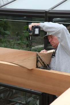
A crew member traces a line 1/4 inch outside the template with a spacer block and then cuts along the line with a 10 1/4-inch circular saw.
Dual-Purpose Templates
After letting the glue cure properly, one of the crew removed the excess dried glue and sanded the faces of the blanks. When they were ready, we set them on blocks on a large worktable.
We’d made two MDO templates—one for each size of cross beam—working directly from the dimensions on the architect’s blueprints. The templates served two purposes: First we used them to lay out for the rough cutting, and then later they became router-bit guides for our initial finished cut.
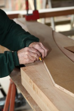
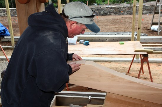
To lay out for the rough cut, we centered the template on the blank with the bottom edge of the template lined up with the bottom edge of the blank and clamped them together. We indexed the template to the blank so that we could reposition it after the rough cut. To mark out for the rough cut, we placed a small, 1/4-inch-thick block of wood against the template and drew a pencil line outside the block. When we’d marked the edges of the beam that needed to be cut, we removed the template and set it aside.
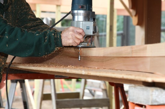
We rough-cut the straight lines of each beam with a 10 1/4-inch wormdrive saw. Unfortunately, the blade did not cut all the way through the true 4-inch-thick lumber, so we finished the cut with a jigsaw equipped with an aggressive 6-inch blade. We used the same jigsaw to cut the arch. Admittedly, a jigsaw does not leave a precision cut, but for this step, our cuts were still 1/4 inch outside the finished surface of the beam.
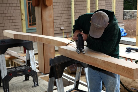
A jigsaw finishes the circular saw cut and then rough-cuts the arch.
Two-Step Routing
With the rough-cutting done, we re-clamped the template to the beam and worktable, taking care to position the template on the beam exactly where it had been before. For the first router pass, we mounted a top-bearing flush-trim bit in a fixed-base router. With the router-bit bearing riding against the template, we cut back the edges of the beam, moving the clamps as necessary to complete the pass. Whenever you’re routing in this manner, it’s always important to push the router against the rotation of the bit so that it cuts into the work without tearing out.
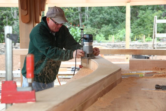
A router with a top-bearing flush-trim bit follows the template for the first finish cut.
The 3/4-inch-diameter bit was removing only about 1/4 inch of material, so it wasn’t over-taxed and stayed sharp for a longer period of time. As soon as we noticed the bit cutting more slowly than normal, we stopped and changed it, usually after cutting three or four beams. The result was a glass-smooth surface that would be easy to sand. But more importantly, we needed that smooth surface to guide our second pass with the router.
The beam is flipped over and an up-cut spiral bit rides on the first surface to finish the cut.
We removed the template and flipped the beam over before making the second pass with the router. This time, we used an industrial-grade up-cutting spiral bit with a double bearing on the bottom of the bit. With the bearings following the surface from the first pass, the bit cut perfectly flush with that surface. The up-cutting action of the bit minimized the chances of tear-out, and again we carefully monitored the sharpness of the bit, changing it before it could start burning the wood. When the routing was finished, each beam received a thorough sanding.
Attachment Strategies
As nice as these beams looked, they also had to be functional, tying together the arbor structure. The cross beams attached to the linear support beams (that formed the T) in two different ways. At all four ends of the T, as well as at the intersection points of the T and at intermediate points along the longer, narrower section, we bolted the cross beams to galvanized threaded rod epoxied into the posts. Structural screws secured all of the other beams in place. Both strategies required accurate placement of the holes to keep the cross beams aligned properly and fastened securely to the support beams below.
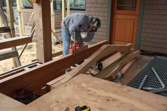
To locate the holes for the through-bolts, we set each beam in place, centered it, and scribed the bolt positions onto the beam. To drill the holes, we started with a Forstner bit that made a large, flat-bottom hole for the nut and washer on the top side of the beam, and a clearance hole on the bottom of the beam for the nut already threaded onto the bolt. We connected the top and bottom holes with a spade bit slightly larger than the bolt diameter to give us a little wiggle room for positioning the beams. After slipping the beam into place, it was just a matter of measuring the overhangs for an exact placement before tightening the nuts.
To locate the holes for the attachment screws, a crew member places a small template on the flat bottom surface of the beam.
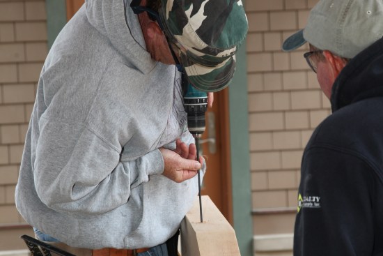
A crew member carefully drills slightly over-size holes for the screws. A Forstner bit creates pockets for the screw head on the top side of the beam.
We used a different approach for the structural screws that attached the other beams. On the bottom edges of each beam, we measured in the distance from the beginning of the arch to the horizontal beam (about 2 inches), and then set a small template in place that located the screw positions.
We drilled guide holes at every screw position, then drilled a hole through from the bottom of the beam to the top while keeping the bit as square to the beam as possible. As with the through-bolts, the bit we used was slightly larger than the thread diameter of the structural screws. After drilling all the way through, we flipped the beam over and chased the holes with a 1-inch Forstner bit, for a flat-bottomed hole for the screw heads to bear on.
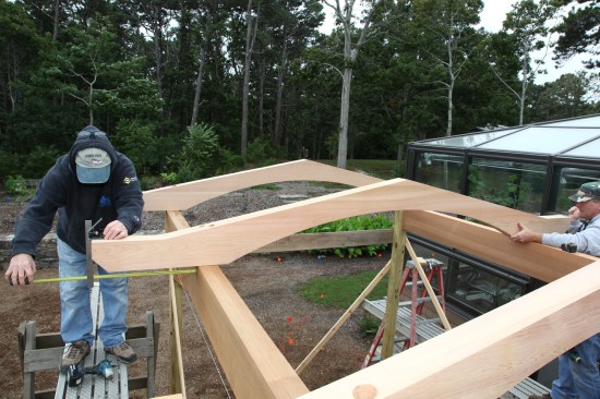
Crew members center each cross beam on the horizontal beams.
After setting the beams in place, we again centered them side to side over the horizontal beams. Because the screws fell on the sides, not in the center, of the cross beams, we took special care to keep the beams vertically square to the beams below as we torqued the screws with impact drivers.
Then they drive the structural attachment screws while keeping the beams square to the top surface of the carrying beams below.
To complete the installation, we cut wooden plugs and glued them into the holes above each fastener. After cutting the plugs flush, the beams were ready to support the glass covering that would provide protection for people walking below.
Photos by Roe Osborn


