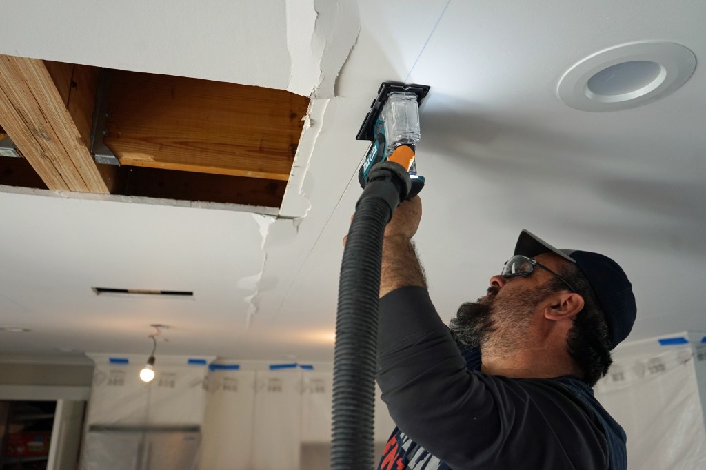
On a recent job completed by my family’s company, Great Lakes Builders, we were called out to look at an unusual condition: The ceiling drywall had buckled along random panel seams near the middle of an open living area (see photo, above). Similar failures were found in other areas on the first floor, which we also corrected, but in this article I will focus on the repairs in the main living room.
The homeowner told us that the building, which is situated a few blocks from Lake Michigan, had originally been a modest ranch house. A large dormer had been added to open up a second floor and capture a lake view, and interior walls had been removed to open up the first floor. The first signs of trouble the homeowner reported were cracks in the ceiling drywall. She called the drywallers back to repair the cracks, and everyone chocked it up to the framing drying. That is, until the repaired ceiling buckled along joints between panels. The drywallers had never seen anything like this and recommended the owner call a structural engineer.
Investigation
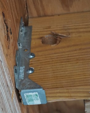
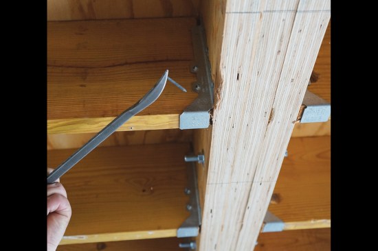
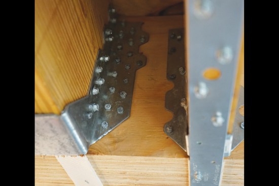
Gaps between the ends of the joists and the LVL beam ranged from 1/4 to 1/2 inch wide.
We began our investigation for the engineer by opening a hole in the ceiling. The engineer needed to verify the type and size of the concealed, flush-framed beam that had been installed during the prior renovation. It checked out to be what had been specified on the plans by engineers for the prior work—three 1 3/4-by-9 1/4-inch LVL plies. New 2×10 floor joists, which replaced the home’s original 2×8 joists, terminated into the flush-framed LVL beam.
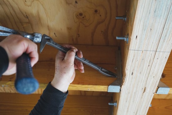
While the framing checked out, we did noticed some irregularities: Nails were missing from the face-mounted joist hangers, and many of the nails that were there had backed out. These proved to be only 1 1/2 inches long, not the 3-inch joist-hanger nails that we would have expected. On closer inspection, we noticed large gaps—from 1/4 to 1/2 inch wide—between the ends of the joists and the LVL beam (see photo, above). This is much wider than the 1/8-inch maximum allowed for code-accepted standards on face-mounted joist hangers. We speculated that the framers might have originally built the new floor expecting an undermount beam, and then switched direction when they noticed it was a flush beam. There were clear signs on the underside of the floor sheathing that the joists had been cut off with a recip saw—not what you’d expect for installing new joists.
We also noticed that one side of the LVL beam was plumb while the other side was out of plumb, suggesting to the engineer that the LVL plies had separated. And as it turned out, the LVL plies had been secured on each face only with two rows of small (3/16-inch-diameter instead of 5/16-inch) structural screws on 32-inch centers, with the rows staggered at 16 inches. That was not nearly enough fasteners for this beam, in the engineer’s estimation, accounting for one of the plies rotating out of plumb.
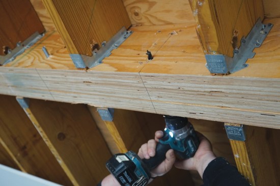
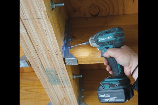
Repair work began with drilling for 1/2-inch threaded rod on 16-…
Causes
Ultimately, the engineer concluded that the buckling was caused by a combination of forces:
- Lateral loads from the winds coming off the lake pushed and pulled at the floor framing, and the gaps between the joist ends and the LVL beam, along with inadequate nailing of the joist hangers, allowed the joists to move.
- Side loading of the joists on the LVL would ordinarily not cause any shift in the structure if a beam is sized adequately and the LVL plies are tied together securely so the beam acts as a single unit. In this case, without adequate fasteners, the plies pulled apart.
Seasonal humidity swings. In addition, changes in seasonal humidity caused excessive movement in the framing. These seasonal changes were higher than normal, the engineer reasoned, because of the absence of vapor, air, and thermal controls in critical areas of the building. Inspection holes along the side of the house revealed rusty nails and black joists and floor sheathing, caused by air and moisture intrusion. In this region of the country, cold winters with very dry air, springtime inversions that create a lot of fog over the lake, and very humid summers all result in huge swings in outdoor relative humidity. These conditions accentuate the need for vapor and air barriers to keep interior wood framing near equilibrium moisture content, as well as good insulation to combat condensation. To overcome these challenges, part of the engineer’s repair plan included spray foam insulation installed along the rim joist and in critical wall sections of the dormer that was funneling air into the floor structure. Our scope of work involved only the structural repairs, so this insulation work happened after we had left the job.
Repairs
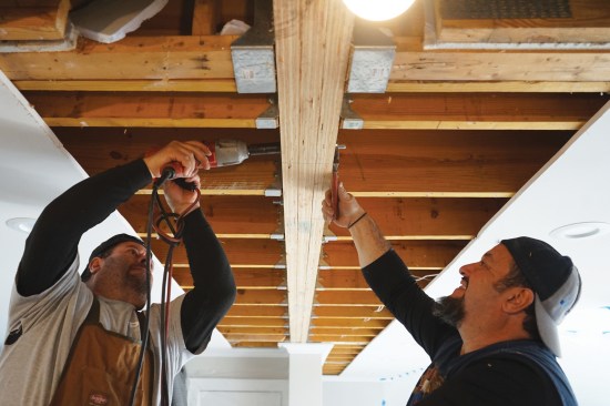
We began by stripping the drywall off the ceiling to expose the full length of the flush beam, opening the ceiling on both sides of the beam beyond the panel joints that had buckled.
Through-bolts. With the beam and joist ends fully exposed, we set to work first on installing 1/2-inch-diameter threaded rod with nuts and bolts on each side to draw the beam laminations back to plumb. Working to the engineer’s spec, we placed these 16 inches on-center. When drawing the LVL plies together, we expected a lot of resistance from nails through the sheathing in the upstairs floor. But to our surprise, there were no nails, and the plies snugged up tight and plumb as soon as the nuts were tight.
Secure hangers. Next, we backed out all the 1 1/2-inch joist-hanger nails and replaced these with 2 1/2-inch-long connector screws made by Simpson Strong-Tie. As required for all metal framing hardware, we filled every hole in the hangers.
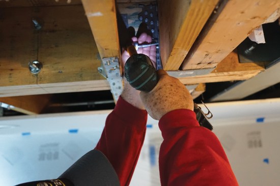
Strap ties. The engineer specified Simpson LSTA24 20-gauge, 1.25-by-24-inch straps at each pair of joists along the beam, centered on the beam and secured with structural screws.
Compression blocks. To prevent the movement of the 2×10 joists, the engineer called for 18-inch-long 2×6 blocks nailed off with 16d nails at the top of the joists butting the beam. These blocks ran into the joist hangers and screw heads, so we had to work at getting a tight connection between the end of the block and the beam.
Joist-wall connection. The repair wouldn’t have been complete if we hadn’t also verified the connections at the other ends of the joists, checking that these were securely fastened and fully bearing on the exterior wall plates. This proved to require little work, but it was important to do.
Through our work, we had taken a lot of disconnected pieces of a floor frame and created a single structural system. This frame still had the gaps between the joists ends and an LVL beam—an unfortunate condition. But the repairs compensated with blocks to resist compression at the top of the joists, and straps to resist tension on the bottom edge. And with the multiple LVLs securely bolted and the hangers fully fastened, we had, in essence, one beam connected to floor joists functioning as a single assembly.


