In the hvac industry, the term “hydronics” refers to any technology that distributes heat (or cooling) using water as the transport medium. Think of a hydronic system as a conveyor belt for thermal energy; the energy can come from a variety of sources and can be released through an equally wide variety of heat emitters (or heat absorbers, in the case of cooling).
JLC readers are familiar with radiant floor heating, the most widely marketed hydronics technology in recent years. During the late 1990s and the early 2000s, hydronic radiant heating saw annual growth rates above 25 percent. The subsequent downturn in residential construction inevitably took its toll on this trend. While hardware for hydronic radiant heating remains widely available, it’s not generating the market growth it did a decade ago. That decline in interest is at least in part because radiant heating came to be perceived as expensive and dependent on complex installations that were costly to maintain and troubleshoot.
There is some truth to those perceptions, but it’s important for builders to understand that there are other kinds of hydronic systems that provide comfortable, reliable heating without the expense and complexity associated with radiant heating. In this article, I’ll focus on hydronic technology that can be incorporated into high-performance, low-load houses and that can make use of heat pumps and solar thermal collectors as energy sources.
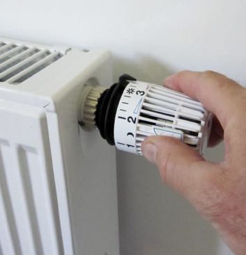
A thermostatic radiator valve provides room-by-room zoning for p…
Adapting Hydronics to Low-Load Houses
Houses that consume far less energy than average pose a different challenge for the hydronic heating designer. Take, for example, a 2,000-square-foot house that is built with SIPs, ICF blocks, or some other super-insulated approach and has a design heating load of only 10 Btu per hour per square foot. If radiant floor heating were installed in 1,800 square feet of this home, the average floor surface temperature would have to reach only about 73°F to maintain the internal air temperature at 68°F, and that’s on a design day (when the outside air reaches the lowest expected temperature for the region). Under partial load conditions, the floor surface might need to reach only 71°F or 72°F to provide enough heat to maintain typical indoor temperatures. Although floor heating could easily satisfy the indoor air temperature requirement – and do so at very low water temperatures – the occupants will likely be disappointed by the lack of “barefoot friendly” floors, which are so frequently advertised as a benefit of floor heating.
There are several characteristics that a hydronic system intended for a low-energy-use home should have. I’ll list them here, then later explain how these design goals play out in specific systems.
Accepts heat from a range of sources. Although boilers are still the most widely used hydronic heat source, modern systems can be flexibly designed to accept heat from devices like air-to-water heat pumps, ground source heat pumps, solar collectors, or a combination of these. This multi-source capability provides versatility in the original installation and also allows for future modification, such as adding thermal solar collectors.
Provides space heating and domestic water heating from the same heat source. This is now standard in nearly all residential hydronic systems. Using a single combustion or refrigeration system to supply both loads reduces both initial and maintenance costs. It also reduces short-cycling, thereby improving fuel efficiency and reducing emissions in combustion-based heat sources.
Provides room-by-room zoning. The ability to control heat output on a room-by-room basis has always been a benefit of hydronic heating. This is equally important in low-energy-use buildings, especially those with the potential for significant and unpredictable internal heat gains. Solar gains through generously sized south-facing windows are a good example. There are several ways to implement room-by-room zoning using hydronics. One of the simplest approaches uses wireless thermostatic valves that regulate flow through each heat emitter.
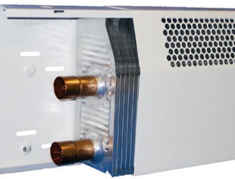
Includes low-temperature heat emitters. The future of hydronics is all about low water temperatures, which improve the efficiency of heat sources like modulating/condensing boilers, solar collectors, and heat pumps. My suggestion is to design all future hydronic systems so that they can meet design heat loads without exceeding a supply water temperature of 120°F. Even lower water temperatures are possible with some heat emitters, including extended surface baseboard and micro-fan-enhanced panel radiators; both of these can be sized to deliver design load output using supply water temperatures as low as 95°F.
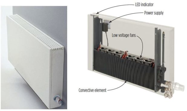
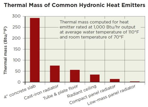
Includes low-mass heat emitters. Energy-efficient houses may be subject to wide temperature variations due to localized thermal gains. To prevent unacceptable temperature swings, it’s necessary to quickly stop heat emission when the desired comfort condition is achieved. One of the criticisms of radiant floor heating – especially those systems where tubing is embedded in slabs – is that it cannot respond fast enough to temperature swings. Low-mass heat emitters, like the panel radiator shown, can react much faster and thus reduce temperature variations.
These masses are based on the amount of heat emitter required to release 1,000 Btu/hr at a supply water temperature of 110°F. Notice that the micro-fan-enhanced low-mass panel radiator has less than one percent of the thermal mass of a 4-inch-thick heated floor slab.
Incorporates parallel piping of heat emitters. Many older hydronic systems connected multiple heat emitters in series, meaning the outlet of one heat emitter was piped to the inlet of the next heat emitter, and so forth. While this may at times be convenient and less expensive from an installation standpoint, series piping can create significant temperature drops from one heat emitter to the next. This requires designers to size each heat emitter based on the temperature of the water where that heat emitter is located within the circuit, which is not always desirable. Series piping also eliminates the possibility for room-by-room zoning and increases the pressure drop of the overall distribution system, making it necessary to use larger circulators with higher wattage motors.
Parallel distribution systems supply the same water temperature to each heat emitter and avoid the pressure drop associated with series piping. Parallel distribution also allows the flow rate through each heat emitter to be independently adjusted. The illustration in Figure 7 shows an example of parallel distribution – a simple home-run system in which each panel radiator is connected to a manifold with its own 1/2-inch PEX or PEX-AL-PEX supply and return tubes. The small-diameter flexible tubing is easy to route through framing cavities, much like electrical cable. Different types of heat emitters can be supplied by the manifold – you could use extended surface fin-tube baseboard in some rooms, panel radiators in other rooms, and a towel-warmer radiator in the bathrooms.
Is self-buffering. Whenever a highly zoned distribution system is combined with a heat source that either operates as an on/off device or has a limited range of heat output modulation, the result is short-cycling – meaning the burner or compressor in the heat source turns on and off frequently. This leads to shorter component life, reduced efficiency, and higher emissions.
In the past, a typical residential boiler might have contained 450 pounds of cast iron and perhaps 10 gallons of water. Those materials made such boilers self-buffering, and thus short-cycling was not a big problem. However, many current-day high-efficiency modulating/condensing boilers have much lower metal and water content. Even with the ability to modulate down to 20 percent of their rated capacity, these boilers can still experience short-cycling when connected to highly zoned distribution systems.
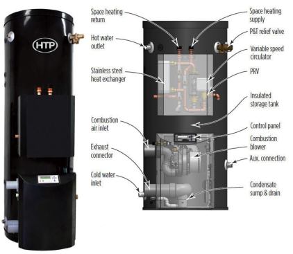
Some heat sources are now available that restore the desirable self-buffering characteristic. One example is the Versa-Hydro combined heating appliance from HTP (htproducts.com), which provides both domestic hot-water and space heating. Depending on the model, the tank contains up to 119 gallons of potable water for thermal mass; this mass in turn “communicates” with the space-heating system through a self-contained stainless steel heat exchanger. The Versa-Hydro is ideally suited as the anchor storage component in a hydronic system for a low-load house. It can also be ordered with an internal coil heat exchanger that allows heat input from solar collectors.
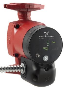
Makes minimal use of distribution energy. A properly designed hydronic system can deliver heat to a building using a fraction of the electrical energy required by a forced-air system. In some cases, the wattage required by the circulator is only about 3 percent of that required by a blower motor of similar heat-transport capacity. This is a tremendous advantage, and unfortunately one that’s not often appreciated by those who focus solely on the thermal efficiency of the system’s heat source.
A modern ECM (electronically commutated motor) pressure-regulated circulator can reduce the operating power requirements for a home-run distribution system in a 2,500-square-foot house to less than 30 watts under design load conditions. One example of such a circulator is the Grundfos Alpha. Similar products are also available in North America from Wilo, Bell & Gossett, and Taco.
Putting It Together
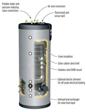
One way to consolidate several of these design characteristics is to build systems around a central thermal-mass unit called a thermal accumulator, like those from Triangle Tube (triangletube.com). From the outside, it looks like a hot-water tank with a few extra connections; inside, though, there’s a lot going on. Under a thick urethane insulation layer is a carbon steel outer tank. The water in this tank can accept heat from a number of external heat sources – a boiler, a heat pump, or solar collectors. It can also accept heat from the internal heat-exchanger coil seen near the bottom of the outer tank. This device can even be ordered with an electric heating element installed in the lower portion of the outer tank, for use during off-peak periods when the price of electrical energy drops significantly. Suspended within the outer tank is a stainless steel inner tank, which holds potable water that’s completely isolated from the water in the outer tank. Thus any heat input to the outer tank can also heat the potable water, assuming the latter is at a cooler temperature. The thermal mass of the water in both tanks provides buffering against short-cycling of the heat source in applications with highly zoned heating distribution systems.
Performance
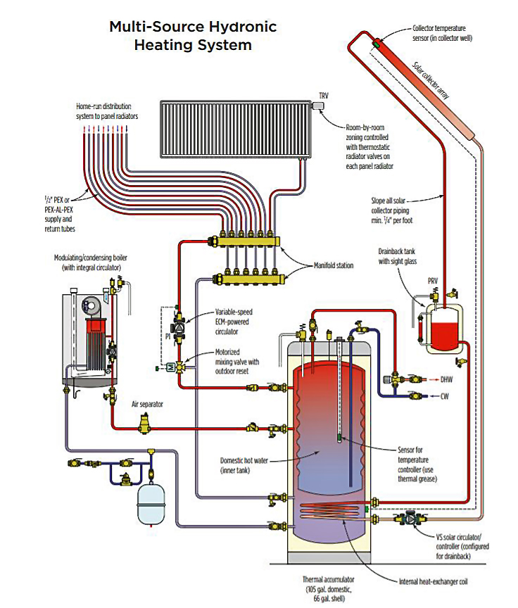
The thermal accumulator can be used as the anchor component in a system supplying multiple zones of space heating and domestic hot water. Heat is provided by a high-efficiency modulating/condensing boiler and a solar collector array. As mentioned before, space heating is delivered by several panel radiators configured in a home-run distribution system. Flow through this distribution system is provided by an ECM-powered pressure-regulated circulator. Each time one of the thermostatic radiator valves opens, closes, or just adjusts flow rate, the circulator varies speed to maintain a fixed differential pressure across the manifolds.
If the sun is out, solar-derived heat is added to the outer tank through the coiled internal heat exchanger. That heat could contribute to either space heating or domestic water heating. Given ample solar heat gains, water within the thermal accumulator could reach seriously high temperatures of 180°F or more. That’s why there’s an antiscald-rated thermostatic mixing valve on the domestic water supply piping. It’s also why there’s a three-way motorized mixing valve to protect the space-heating system from excessively high water temperatures. When the sun can’t sufficiently heat the tank, the boiler is automatically fired to maintain acceptable domestic hot-water temperature.
This system is relatively simple; it provides stable operating conditions and high efficiency and uses very little electricity.
So how might this system perform in the real world? To answer this, I used f-chart solar simulation software to estimate the performance of a combi-system (space heating and domestic hot water) for a sample low-energy house. I assumed:
- design space heating load of 22,500 Btu/hr at 70°F inside and 0°F outside
- domestic water requirement of 60 gallons per day heated from 50° to 120°F
For the solar subsystem I assumed:
- four 4-by-8-foot flat plate collectors
- collector efficiency line intercept = 0.76
- collector efficiency line slope = 0.865 Btu/hr/ft2/°F
- collector slope = latitude +15°
- collector azimuth = 180° (directly south)
- 119-gallon well-insulated storage tank
I ran performance estimates for this scenario in both Boulder, Colo., and Albany, N.Y., calculating he percentage of the total load (space heating and DHW) supplied by solar energy for each month. These results show that you don’t need an entire roof covered with solar collectors to yield a reasonable solar contribution to the total heating load (space heating and DHW) of a low-load house.
There are many other system configurations that would be suitable for low-load houses. Most of them will embody several of the desirable characteristics described earlier. The goal in designing any of these systems is to leverage the inherent advantages of the newest technology while keeping the system as simple as possible.
Be sure to check out the rest of the Radiant Heating Skills Workbook.