A home’s air conditioning system, Kristof Irwin, P.E., likes to say, is like the lungs of the building: As the home’s air supply, the HVAC’s proper functioning is vital. And while the air conditioner itself will likely be replaced in 15 or 20 years (and can certainly be repaired any time), the ductwork is different, Irwin points out: Buried in the ceilings and walls, many duct runs are inaccessible. Once installed, ductwork is what it is—and it may have to serve for the lifetime of the building. As Irwin puts it, “The ducts are infrastructure.”
Irwin is the founder and principal of Positive Energy, in Austin, Texas. Along with providing other services, his company designs high-performance HVAC systems, typically specifying high-efficiency variable-speed compressors and air handlers, paired with dedicated dehumidification and ventilation equipment. Irwin uses the industry standard ACCA Manual J to estimate heating and cooling loads; ACCA Manual D is used to specify the building’s ductwork.
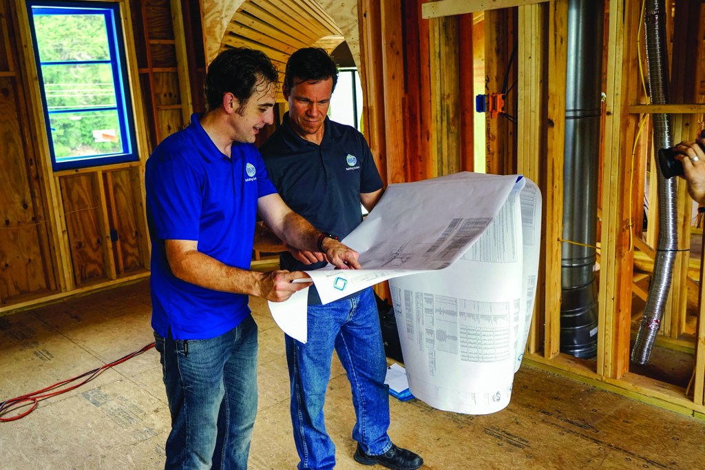
The designs are carefully done, but as Irwin says, “You don’t live in the design. You live in the house.” That’s why Positive Energy also tests air-conditioning duct systems during construction to make sure they’re performing as intended. On a recent trip to Austin, JLC went on site with Positive Energy’s Sean Harris to see for ourselves how the company’s duct testing works.
Tim Healey
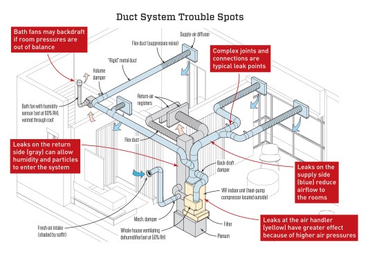
The drawing above, adapted from a Positive Energy design rendering, shows the anatomy of a typical duct system connected to a high-performance air conditioner. Positive Energy has specified dedicated dehumidifying equipment, a ducted fresh air supply, and bath exhaust fan details in addition to the air conditioner and its ducts. The design calls for metal ducts, except for short runs of flex duct at registers to reduce noise. If the design is correctly installed, testing should not reveal any trouble.
WHY TEST DUCTWORK?
Building-science consultant Sean Harris is Positive Energy’s lead field inspector for ductwork and building envelopes. On the job we visited, Harris was measuring airflow and leakage of installed ducts in a home under construction by builder Risinger & Co.
Harris wasn’t expecting to find discrepancies on this job. Air Rite By Design, the HVAC contractor, is known for meticulous work, he says. Still, duct leakage testing is required by code; Austin adopted the requirement years ago, and the national model codes have also begun to require leakage testing.
It’s not just about compliance with the building code, however. There are significant performance reasons to care about duct leakage. “There are three main types of leaks,” Harris explains. “Supply-side duct leakage, equipment leakage, and return-side duct leakage.” Each type of leak can cause specific problems.
Supply leakage. Supply ducts and registers provide filtered, conditioned air to rooms in the house. If those ducts are leaky, says Harris, “you don’t get the airflow to the rooms.” But there’s a twist: Holes in a supply duct don’t necessarily blow—sometimes, they suck. “There’s a thing called the Venturi effect,” Harris says, “where air flowing past a hole in a positively pressurized duct can actually pull things like insulation dust into it.”
“Even when the system is not on,” Harris continues, “and there’s no fan blowing, a duct leak is still a building-envelope leak.” When he’s inspecting ducts, Harris says, sometimes he’ll notice a puff of air leaking out of a supply duct into an attic just because somebody downstairs has opened a door to the house.
And when the air-handler fan is running, supply leaks can depressurize the entire house. Harris often sees that in older existing homes: “27% of duct airflow is the average leakage here in Austin,” he says. “Let’s say it’s a 2.5-ton unit, with 1,000 cfm of airflow. That [27%] means 270 cfm—a quarter of the air—is leaking into the attic. Well, the unit wants to find that missing 270 cfm somewhere. That deficit is going to be made up from light switches, outlets, penetrations in the drywall, leaky windows, and things like that.”
Despite conventional wisdom, says Harris, supply-side leakage is a concern even if the ducts are technically in conditioned space. In one recent case, Harris answered a call from a homeowner who had mold growing on her bathroom ceiling. In that example, he explains, “the duct leakage was isolated to the spray-foamed attic space. There was a good ceiling-plane seal where the drywall was. The 200-cfm leakage into the attic was causing a 19-pascal depressurization on the house, and because the house was so tight, the pressure difference pulled from the exhaust fans in her bathrooms. All that heat and humidity was coming into the bathrooms from outside, and she was getting mold on her bathroom ceilings. But the root cause was supply-side duct leakage.”
Equipment leakage. “Coil cabinets and furnace cabinets leak,” says Harris. “And they leak a lot. All those seams, and points where the refrigerant and drain lines go through—those things suck or blow air. And the closer you get to the fan, the more every hole contributes to leakage, because there’s a greater pressure difference across that hole. Smaller leaks count for more when you are closer to that fan. And of course, all those leaks cause the same kind of problem as I’ve already mentioned.”
Return leakage. Air leaks in a home’s return ductwork create their own brand of trouble, says Harris. “You’re pulling air straight in from wall cavities and attics, including unconditioned spaces. Now your coil has to deal with the higher latent load of that incoming humidity. The system won’t be able to take that moisture out in one pass—which means that you’ll be cycling a lot more humidity through your house and your system.”
Return leaks from unoccupied spaces such as attics are a problem, Harris emphasizes. “It’s often a dirtier space, with a wider range of particle size. Your filter is not going to stop all of the particles from going through. But the main thing when you pull from an attic is the heat and humidity that you pull in. The filter doesn’t filter either heat or humidity.”
“Then there are particulates,” Harris continues. “If the leak is before the filter, then the filter catches most of the particulates. But if you have leakage after the filter, material can build up on the coil. Eventually, that may impact airflow; but more importantly, the coil is the coldest surface in your house. It’s designed to be at the dew point. It is supposed to stay wet, so that you can dehumidify. And if stuff builds up on it, you’ll grow mold on the coil.
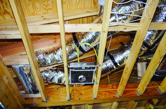
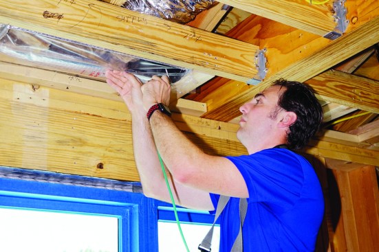
Ductwork installed in this high-end custom home under construction will be difficult to access after the ceilings are drywalled.
At this point in the job, however, the air handlers have not been installed.
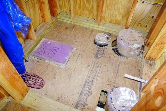
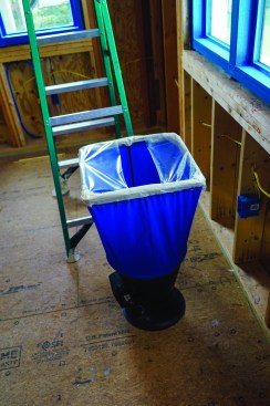
Instead, supply and return duct runs are capped with plastic wrap and tape in the mechanical room.
Positive Energy duct expert Sean Harris will test the duct system now, and then return later in the job to re-test the fully assembled system.
FINDING THE FLAWS
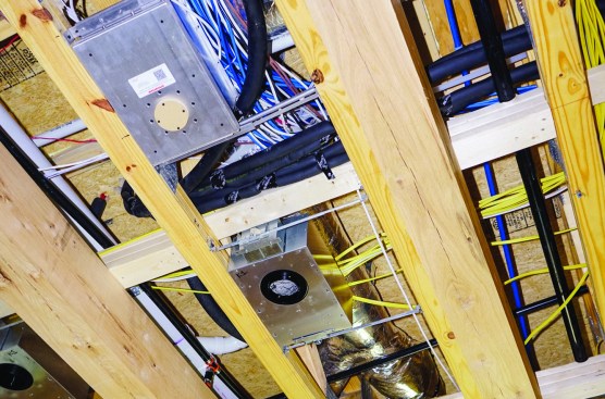
In a brand-new home, Harris says, a by-the-book design should perform as intended—as long as it’s installed correctly. Anybody can make a mistake, though, he notes—and in any case, last-minute changes that affect the ductwork are common. “Very rarely does a job go exactly as planned,” Harris notes; for this project, Positive Energy had to modify the distribution systems for several zones after a preliminary walk-through, to adjust to changes in structural framing and truss configurations. And since the systems can’t be easily modified once drywall is complete, it’s important to verify the effect of the changes while ducts are still accessible.
Pressure testing to detect air leaks is the first step. “I like to test with as many pieces of the puzzle together as possible,” says Harris, “because ducts don’t leak in the middle—they leak at the connections. The more connections that are in place for me to test, the better feedback I can give to the builder and the HVAC contractor.”
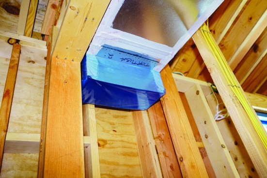
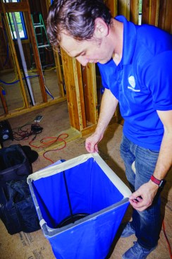
Air-handler equipment is typically installed late in the job sequence, however, to reduce the risk of theft or damage. And in this case, the sequence of trades was a factor: Plenums and equipment couldn’t be installed until the wall of the equipment room was insulated and drywalled. So Harris had to test the ducts before they were hooked up to the air-handling equipment. He started by masking off the stubbed-up ends of duct trunks entering the mechanical room (see photos, above).
Next, Harris attached his Minneapolis Duct Blaster (energyconservatory.com) to the duct system. “When I hook up to the main source,” he says, “it’s important for me to look at the plans. I have to make sure that I haven’t missed anything that I need to seal off, and check that the locations on the plans match up with what is there in real life.”
To prepare for pressure and airflow testing, Harris attaches the Minneapolis Duct Blaster’s collar to the end of a supply duct, sealing the inside of the collar.
He seals the outside with tape.
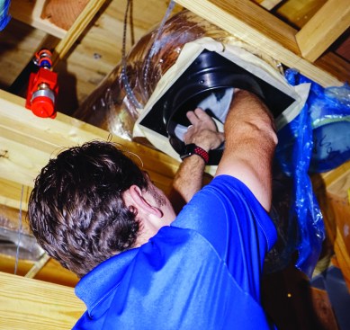
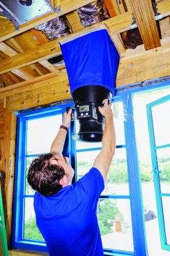
Next, Harris inserts the end of the Duct Blaster manometer’s pressure-sensing air tube into the taped-off end of the duct. When the fan is up to speed, the device’s DG-700 pressure and flow gauge will calculate the duct run’s air leakage.
In this case, after taping off all the duct registers, Harris connected the end of the Duct Blaster to the end of a trunk line in the ceiling of the mechanical room, then inserted the pressure-sensing air hose for the device’s manometer into a supply duct register. Then he powered up the Duct Blaster for a pressure test .
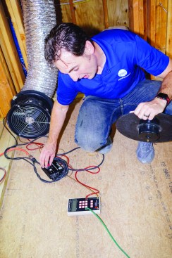
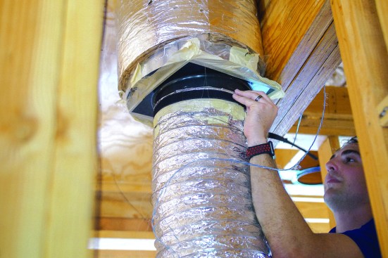
After hooking up the Duct Blaster, Harris adjusts the fan controls to bring the pressure in the system to 20 pascals.
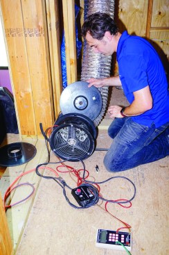
By itself with no-air handling equipment hooked up, the duct run is remarkably airtight—so airtight that to get meaningful numbers, Harris has to insert a “Ring 4” flow restrictor into the fan assembly.
With the flow restrictor in place, Harris recalibrates the pressure and flow gauge, and uses his smartphone to calculate the equivalent leakage rate.
As it happened, the leakage for this run of ducts was so low that Harris had to insert the smallest available flow-restricting ring (known as “Ring 4”) into the Duct Blaster, then use a lookup table on his smartphone to calculate the leakage rate based on the modified fan speed and pressure.
If the system shown in this story were complete, he notes, the calculated level of leakage (9 CFM25) would have been extraordinary. But only after the equipment was installed would he see final numbers for the whole system. “I’m not looking for just a pass or fail on duct leakage at this point,” he explains. “I’m thinking about the big picture.” This test did establish that the ducts would not need to be fixed before drywall.
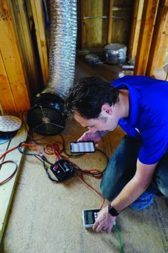
With the leakage test complete, Harris moved on to the airflow test, using an Alnor LoFlo Balometer Capture Hood, manufactured by TSI (tsi.com). “I take down all the tape off the registers, and I turn up the fan, and I make sure that the fan is putting out roughly the amount of airflow that I should have through the duct system,” he explains. “Then I can see how balanced the rooms are in relation to each other. If I find major imbalances, I need to figure out what is going on. Maybe we have to put some dampers on. Or maybe the installers used the wrong duct size, and one room has a duct that is too small.” In one case, Harris actually detected a duct run that was completely blocked: “The trunk line never got cut in at the plenum. Once the duct was attached, you couldn’t see it, and nobody caught it until I was there to test.”
The Alnor flow hood measures airflow through a supply register.
Because he’s testing the system with no drywall installed, Harris masks off the parts of the flow hood that would ordinarily be blocked by the drywall.
On this house, Harris didn’t find any deficiencies. That’s not surprising, he says. “If the air-conditioning contractor follows our design to the T, they shouldn’t have to balance anything. Sometimes I go in and measure, and I get the exact numbers that we designed for that space.”
Then, with the Duct Blasterfan set to supply the design airflow for the system, he checks the output of every register in the rooms served by this duct run, to make sure that the actual flows match the design values for the system.
“In our industry,” says Harris, “there are still some people who don’t understand how duct design works. They think that a rule of thumb from the 1980s is still how it’s done. But that’s not the case. For airflows, fluid dynamics works, and there are simple software tools out there that accurately predict how much air you are going to get out of that duct. And when it is installed exactly as we design it, we actually get that delivered performance.”


