Even after 30 years of specializing in stair building, I occasionally come across a new challenge that really gets my attention. Earlier this year, one of the builders I work for asked me to recreate the Craftsman style of the stair in his own home for a new house he was building. He showed me
photos of his newel post and railing components, purchased from a millwork manufacturer. However, since this new house was being built on spec, he wanted to keep the cost down and wondered what I could do about that. After reviewing the details, I felt that I could site-build the newel and baluster assemblies using relatively inexpensive components and off-the-shelf materials and still produce the desired quality and effect. While I did build the entire stair, in this article I’ll focus on the newel and baluster construction.
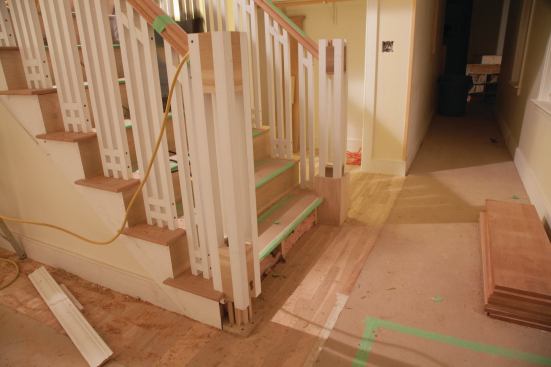
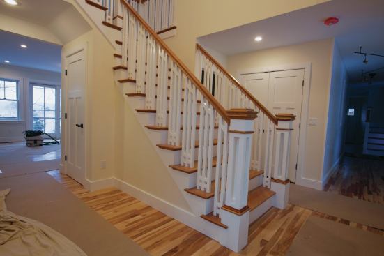
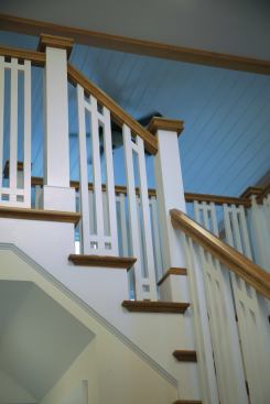
The newel could be described as a nominal 6×6 box-type post with an open center “cage” defined by a square baluster at each corner. A plain, solid wrap topped with molding creates a beefier base profile, while flush infills close the cage at the top, crowned by a beveled cap.
Click to enlarge image below.
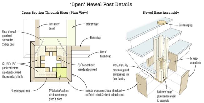
At top and bottom, infill spacers and backer blocks add strength and help with alignment of the newel cage. The original plan called for fastening the newel base to the first tread and anchoring full-length rear corner balusters to solid blocking behind the riser. After the client changed his mind, the modified newel was anchored to the floor and to blocking behind the first riser.
All well and good, but a newel post has to be stiff, strong, and solidly attached to serve its function. And for efficiency, rather than assembling them in place piecemeal, I wanted to build and install the posts as complete components while using as few visible fasteners as possible.
The balusters, unified in decorative grids of three per tread, presented a challenge of their own. A pair of flush-set crossing blocks ties them together at the base, parallel to the treads, while a single crossing block at the top follows the slope of the railing. I’ll describe the newel-post assembly first, and then move on to the balusters.
Making ‘Open’ Newel Posts
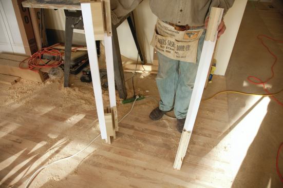
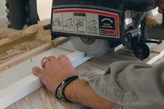
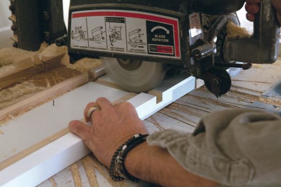
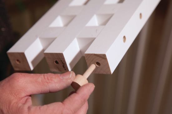
I based the construction of the newel posts on 1 3/4-inch-square pre-primed poplar balusters. I assembled them in an open box-post configuration, tying the four sides together at the top and bottom with 5/4 solid poplar infill (see “Cross Section Through Riser” illustration, above).
Dave Holbrook
The main stair newels were site-built from 1 3/4-inch-square pre…
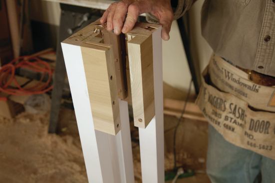
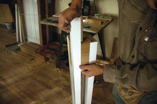
To minimize the number of visible fasteners, I glued and screwed 3/4-inch backer-blocks, or cleats, to the back side of the four balusters and the infill pieces. These not only provided concealed fastening but also strengthened the assembly and helped with positive alignment of the components. I was able to assemble three of the four corners in this manner. I made the fourth corner the same as the other three, but installed it by sliding it down into place after applying yellow glue to the backers and then clamping it.
The builder’s original intention was to have the newels mounted on the first tread. I had already assembled the newels when he decided that they’d look better mounted on the floor in front of the first riser. Although I’d already trimmed the rear corner balusters, fortunately I’d let the backers run sufficiently long to convert to the new location without having to reconfigure the posts (see “‘Open’ Newel Post Details” illustrations, above).
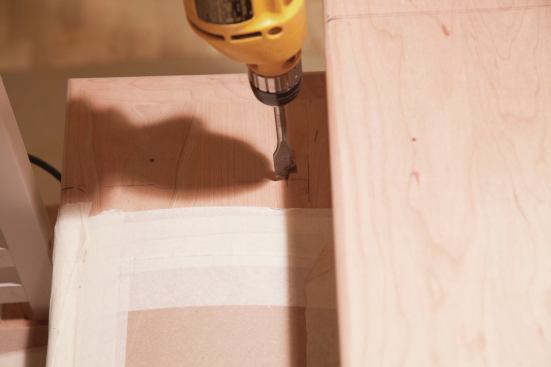
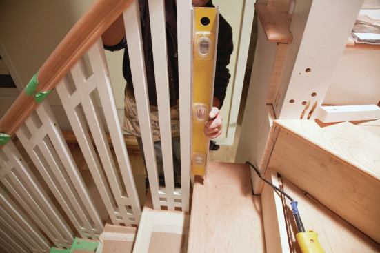
To attach the post to the floor, I first made a 5/4 base plate sized to match the square 5 1/2-inch profile of the overall post. Then I trimmed the backers to match the height of the first riser—allowing for the thickness of the base plate—glued and screwed them to the base plate from the bottom, and glued and screwed the whole assembly to the floor. I also drove a couple of long screws through the rear corner balusters into blocking behind the first riser.
Next I added a 1-by poplar wrap around the base, mitered at the corners and a few inches shorter than the infill pieces, creating an offset profile to the post. The wrap, scribe-fitted around the nosing, provides a reinforcing connection between the post and the base plate. I set the post into the starter tread so that its backside occupies the position that’s otherwise taken by the first baluster on the common treads, typically with its front face flush with the finished riser.
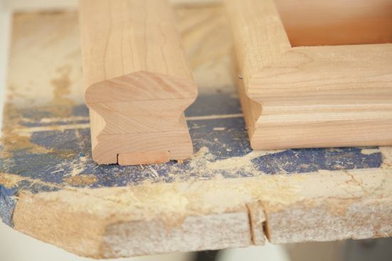
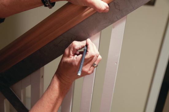
I let the top corners of the newel run long to allow me to visually center the railing on the post. Once I’d attached it, I trimmed the tops square and level. I applied a contrasting cherry molding around the top of the base wrap and below the railing connection at the top of the post.
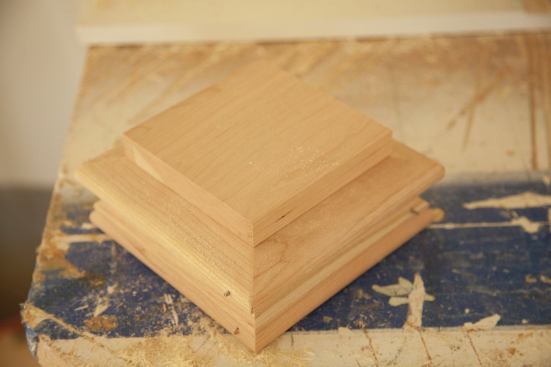
While it would have been possible to order a decent-looking manufactured post cap, I wanted the post cap profile to match the railing, so I made custom post caps. I ordered an extra length of the cherry handrail, ripped it down the middle on the table saw, then mitered four pieces together to frame the basic cap.
To ensure a tight fit between the cap frame and center cover piece, I slightly back-beveled the top edge. To make the cover piece, I used 1-by cherry with its edge rabetted to form a drop-in lip. I rounded the edges with a router, glued the cover on the cap, then simply glued the assembled piece, using construction adhesive, to the top of the newels. The remaining “leg” of the railing stock’s baluster plow effectively covers the connection joint.
Baluster Assembly
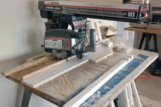
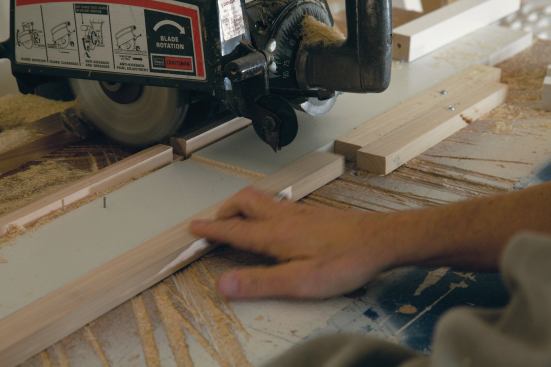
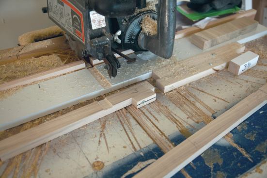
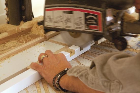
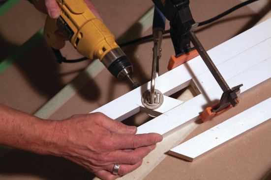
For economy as well as accuracy, I always strive to produce all the common parts of an assembly in a single dedicated operation. To do so, I set up multiple tool stations according to the task at hand. To make a half-lap interlock between the center 1 1/4-inch balusters and the cross blocks, I used a 3/4-inch stack dado blade in my radial arm saw. Since the cut required two passes to create the full 1 1/4-inch-width required, I ripped two 1-by stops to the same width as the balusters, screwed them side by side to the saw table, and offset them from each other to give me an exact 1 1/4 inch plow halfway through the piece. Holding the workpiece against the first stop produced the left-hand cut; then I inserted a place-keeper against this stop to move the workpiece out and against the second stop, which produced the right-hand cut and finished the plow.
Dave Holbrook
The balusters came predrilled to accept wood pins that anchor th…
To produce the plow for the second parallel block, I made a set of removable place-keeper sticks that I labeled with a number to make sure I didn’t confuse them with any of the other stops and blocks I was using. Held against the permanent stops, these sticks controlled the location and the width of the bottom plow.
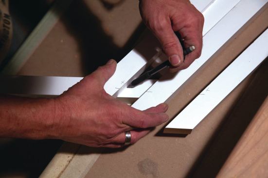
The cross blocks determined the overall width of each baluster assembly. To make them, I first cut enough baluster stock for all the blocks I’d need, to a length slightly more than twice that of a finished block. When cut to finished length, one piece would yield a pair of blocks for each baluster assembly. Next, I cut and labeled a pair of stop offsets from baluster scrap to give me a 1 1/4-inch-wide plow across each end of the workpiece. I then used my chop saw to cut the pieces against a stop clamped to the fence, flipping them end-for-end to make two finished blocks per piece.
The quality of manufactured stair parts varies, and I know better than to expect perfection in every line. (At least, I should.) Even within the batch of prefab, pre-primed, 1 1/4-inch-square balusters I ordered, I found a discrepancy in thickness between one piece and the next. Fortunately, I’d paused for a dry-fit and found 1/16-inch slop in the fit between pieces. This prompted me to stop and cull through the balusters, picking out enough uniform 1 1/4-inch stock to make all the cross blocks.It’s possible that I had stumbled on the only undersize piece in the batch because I had no further problem with the fit in the other direction, where the block might fit tight top-to-bottom, but a “skinny” center baluster would leave a vertical gap.
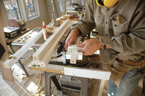
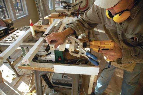
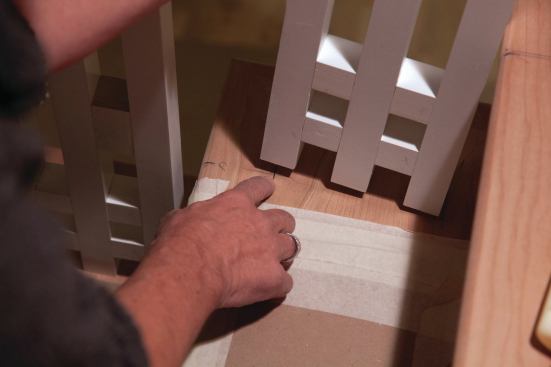
To assemble the baluster units, I glued each of the two bottom cross blocks into the center baluster, then laid the two outside balusters alongside, using temporary spacer blocks at the top to maintain parallel alignment. After lining up the baluster ends, I used a Kreg clamp to hold the block and baluster faces flush, then drilled countersunk holes and screwed the balusters to the blocks. The screw holes received wood plugs, sanded flush and painted, after installation.
As a final note on the baluster preassembly, I allowed an extra 1/4 inch beyond what was needed for finish length. Because there are small variations in riser height—as well as cups, crowns, and slight deviations from level in the treads, all of which occur in a typical stair—I planned on scribing each baluster assembly to an exact fit between tread and railing.
Baluster Installation
As mentioned, I expected small variances in riser height and tread flatness, so I individually scribed and cut each baluster unit. For ease of installation, I also planned not to anchor any of the middle balusters.
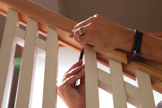
Balusters typically come with their ends predrilled deep enough to allow for some trimming while still accepting the LJ-PIN EZ wood dowels that anchor them to the tread surface. However, some of those holes are centered in the piece and some aren’t. Because of the off-center pin issue, I didn’t immediately drill both holes in the tread. Instead, I located the railing centerline on the treads and drilled the 3/4-inch hole to receive the rear, or longest, baluster. Before drilling, I checked the pin location by eye and if it was off-center left or right, I adjusted the hole location to one side or the other of the centerline. Next, I whittled a pencil down and inserted it into the pin hole in the front or shortest baluster, again eye-balling the hole for off-center left or right. I then dry-fit the pin in the long baluster, positioned it in the hole in the tread, and swung the whole baluster assembly across the centerline to transfer a pencil mark to the tread for the second pin, adjusting left or right, if necessary, for an off-center pin hole. It worked like a charm. I checked the fit of the balusters against the tread, scribing and trimming as needed to eliminate any gaps.
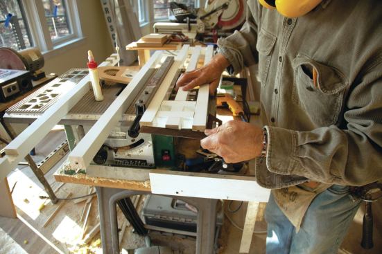
Next, I plumbed the assembly against the railing and marked the top ends for cutting. I added 3/8 inch in parallel to these marks to allow for the plow in the railing’s underside that houses the balusters. I also marked a parallel line across the balusters to locate the angled top cross blocks, thus ensuring a true, consistent line from one baluster set to the next.
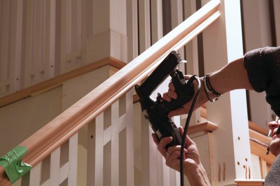
I laid the assembly flat on the workbench, placed temporary blocks between the balusters to maintain accurate spacing, and trimmed the end angles on a chop saw. I scribed and cut the angled cross blocks and installed them, gluing and screwing them from the outside and brad-nailing the interior connections.
With each set of balusters custom-fitted to its location, I glued in the dowel pins and tipped the assembly into position, easing the top into the railing plow. Given that the baluster was 3/8 inch taller than the space between the rail and the tread, I was concerned that I’d have trouble finagling the wider triple-baluster assembly into position and that I’d have to lift the railing off and set it down after all the balusters were placed. But as it turned out, a group of three went in as easily as a single one typically does.A couple of brad nails fixed the tops against the railing.
To finish up, I scribed, cut, and installed fillets (fillet stock ships with the railing) between every last baluster, effectively locking them in place. I glued wood plugs in all of the countersunk screw holes and sanded them flush.
I made the balustrade around the second-floor stairwell in a similar fashion—with the exception that the newels are simple 4×4 posts with smaller custom caps.
The painting crew did a great job sanding and filling the minor imperfections, and I wasn’t the only one happy with the finished installation. In all, the complete stair took about 48 hours to install, and about eight of those hours were spent installing the newels and railing.


