Ah, Los Angeles: home of the Dodgers, the Lakers, and Hollywood. The City of Dreams has not only produced some amazing disaster movies over the years but has experienced numerous disasters off the screen as well. The city and surrounding counties have endured winter storms washing away beachfront houses and wildfires burning homes to cinders, along with mudslides, floods, and earthquakes, with the prospect of next “big one” looming in the back of many an Angeleno’s mind.
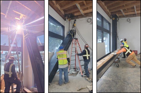
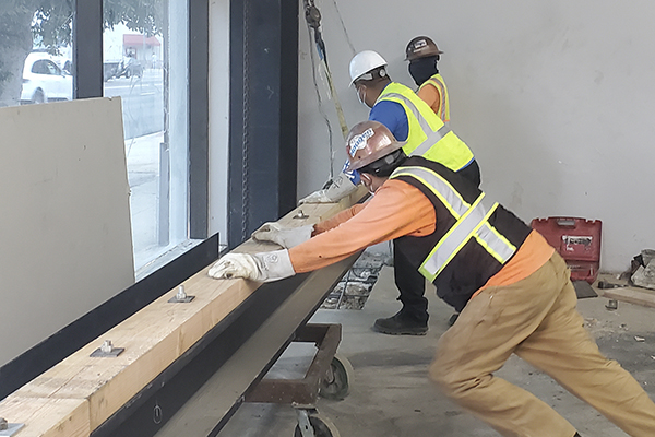
Ironworkers assemble a moment frame needed at the storefront entry.
The LA basin has witnessed many major temblors: the Long Beach quake (1933), the Sylmar quake (1971), and the Whitter (1987) and Northridge (1994) quakes, to name a few. According to the California Earthquake Authority (CEA), the last “big one,” the Northridge earthquake and its spawn of aftershocks, caused an estimated $20 billion in damage—nearly $35 billion in today’s dollars—to thousands of residential structures alone. I’ve been a licensed building and remodeling contractor in LA since 1980 and have lived through the Sylmar, Whitter, and Northridge quakes. I spent the better part of a year repairing earthquake-damaged homes, their knocked-down chimneys facing due south as a result of Northridge’s violent northward thrust.
Recently, I was contacted by owners of a commercial building seeking to make their investment property as earthquake resilient as possible. They were worried the building might not survive the next big quake because of its proximity to a major fault line, the Inglewood Fault (also called the Wilmington Blind-Thrust fault).
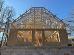
A plucky structure. The dust from the 1933 Long Beach quake had barely settled when construction began in 1934 on what would be a new Packard car dealership. It was built with 12-inch-thick concrete walls and covered with a conventional wood-framed roof supported by bowstring trusses constructed on-site. In the intervening years, this 2,500-square-foot piece of history has served as a Saab dealership, an independent Porsche repair shop, a wheel and tire business, and most recently, a shop selling vans modified with ramps for people with disabilities. The 87-year-old structure has managed to survive every quake since its inception—no small feat considering the devastation the city has suffered over the years.
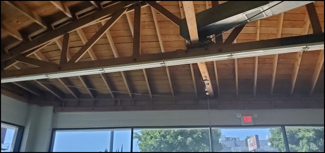
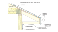
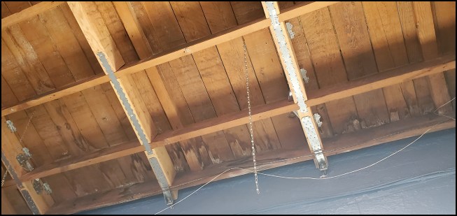
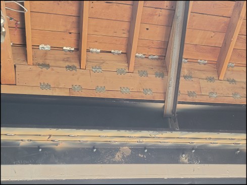
The 2-by rafters transition from a bowstring truss to a ledger above a wall-to-wall storefront entry in the showroom area.
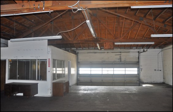
Existing bowstring trusses and 2-by rafters in the open garage portion of the building.
While inspecting the structure three years ago, I noticed the 12-inch-thick poured concrete walls were in good shape for a building of its age, but the connections tying the roof to the walls were woefully inadequate. Where the 2×8 rafters ran perpendicular to the walls, the rafter ends were connected to the wall by steel rods embedded in the concrete. The ends of the rods, bent 90 degrees to form short, 2-inch-long legs, were inserted into holes drilled in the ends of the individual rafters and held in place with some bent-over nails (author’s sketch). Also, the ends of the bowstring trusses were held in place by steel brackets buried in the concrete walls, and if a quake strong enough to pull them free occurred, there would be nothing left to support them. We’d therefore have to provide posts at all the truss locations.
I recommended a respected structural engineering firm, which the owners approved. The firm then ordered “as-built” drawings showing the dimensions of the building.
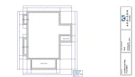
A big opening. The L-shaped, single-story building was divided into three parts: an open garage, a sales office, and a showroom. The showroom (and part of the sales office) occupied the short leg of the L-shaped building. A notable characteristic of the showroom wing was its nearly 45-foot-long open storefront entry and window wall, which ran at an angle conforming to the city street grid layout beyond (see roof framing plans below).
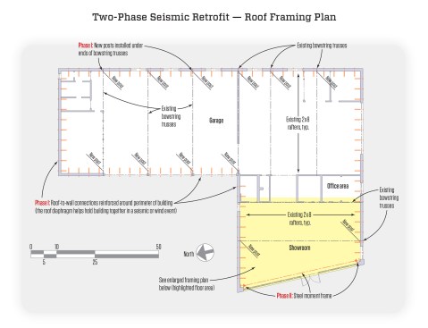
The L-shaped, single-story building is divided into three parts: an open garage, a sales office, and a showroom. The seismic retrofit was done in two phases; first, required roof-to-wall and truss-to-post connections were installed, then the steel moment frame.
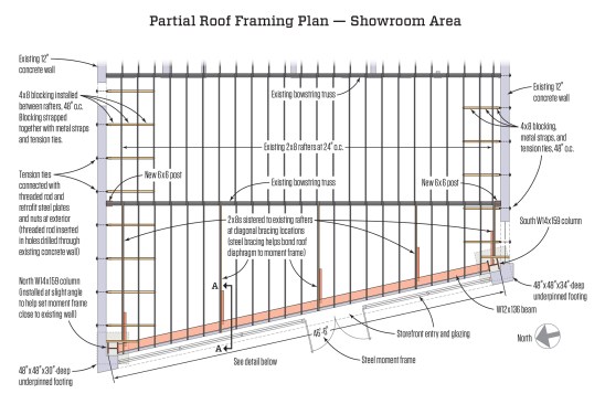
A new 46-foot-6-inch-long moment frame was needed at the angled wall-to-wall storefront opening.
Rafter ends would be connected to the moment frame via 2-by blocking and metal clips.
In the 1970s, the building was remodeled and two central concrete posts along the angled wall were removed to create a wider glazed storefront. The previous builders had constructed a heavily reinforced Z-shaped lintel to span the nearly 50-foot width of the showroom’s end wall, bearing it on two 18-inch-thick concrete columns at each end. The engineer’s assessment noted that a moment frame would be needed at this angled, fully glazed end wall to resist potentially strong lateral forces brought on by a major temblor.
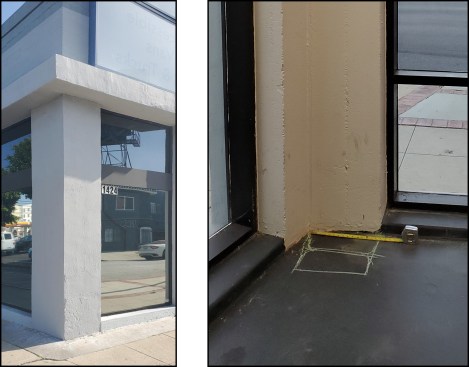
Moment frame. One of the two concrete pillars supporting a Z-shaped lintel (left). Column layout for the new moment frame, south corner (right).
We planned to complete the seismic retrofit in two phases: First, we would work around the building’s tenants, installing required roof-to-wall and truss-to-post connections, and then, during the tenant’s slow sales season, we’d begin the more invasive work installing the steel moment frame.
Phase 1: Tying the Roof to the Walls
The structural design relied on the roof diaphragm to hold the building together in a seismic or wind event. This meant beefing up several roof-to-wall connections around the perimeter of the building. Where the rafters ran parallel to the wall, we installed 4×8 blocks at 4 feet on-center between the existing 2×8 rafters in the first three bays from the wall. We then strapped the blocking together with Simpson Strong-Tie ST6236 straps and nailed Simpson HTT5 tension ties to the blocking abutting the wall. After drilling a hole through the 12-inch-thick concrete wall, we connected the tension ties with 3/4-inch galvanized threaded rod and octagonal Simpson RP6 retrofit steel plates secured with nuts on the face of the exterior wall. We nailed Simpson A35 framing clips to the rafters and screwed them to the 1-by roof deck boards (in lieu of removing the roof materials and providing boundary nailing and re-roofing).
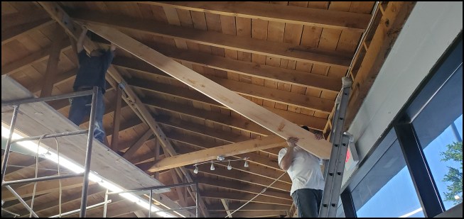
Roof connections. Crew members sister new 2x8s onto existing rafters at steel angle diagonal brace locations above the storefront entry.
Roof connections. Between rafters parallel to the wall, 4-by blocking was added and secured with metal strapping and tension ties.
Where the rafters ran perpendicular to the walls, we attached HTT5 tension ties to the ends of the rafters, 48 inches on-center.
In the garage area, we sistered new 2×8 rafters to every third existing one and connected HTT5 ties similarly (through-bolted with retrofit steel plates and nuts on the exterior).
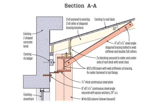
In the showroom wing, the rafter ends were connected to the moment frame via 2-by blocking and steel connectors, bonding the roof diaphragm to the moment frame. See the section detail, at left.
Supplemental posts. In addition to beefing up the connections, we also had to add support, so we installed new 6×6 Doug-fir wood posts in most locations under the ends of the existing bowstring trusses. We secured the post bottoms with Simpson AB post-base connectors set into the thickened edge of the existing concrete slab with epoxy anchors, and at the top, we married the posts to the bowstring trusses with custom-welded saddles. I opted for steel columns at the garage door locations, having seen my share of wood posts damaged by workers backing into them on jobsites.
Phase 2: The Moment Frame
We completed the bulk of the roof-to-wall seismic retrofit work, then the project hit a nearly two-year intermission. The tenants didn’t want to close the showroom. “Wait until September when our sales taper off,” they said. Well, September came and went as did many more months until the pandemic shut the world down. More waiting. Then the tenants finally moved out and we invaded the empty showroom to complete work on the steel moment frame. Our steel costs more than doubled (from approximately $30,000 to more than $60,000) over that time.
The engineer’s design called for a massive moment frame with a 45-foot-long W12x136 steel beam weighing approximately 6,100 pounds and two 13-and-half-foot-long W14x159 columns weighing roughly 2,145 pounds each. When deciding during preconstruction planning how to install these heavy steel members, our first idea was to cut a hole in the roof and crane them in place, but the Z-shaped concrete lintel blocked access from above (also, cutting a hole in a perfectly good roof wasn’t an idea I relished). Using a forklift was not an option, as its mast would hit the ceiling lifting the beam upward. Consulting with the ironworkers, or steel fabricators as they’re referred to in California, we decided to lift the beam and columns in place old-school style with chain hoists.
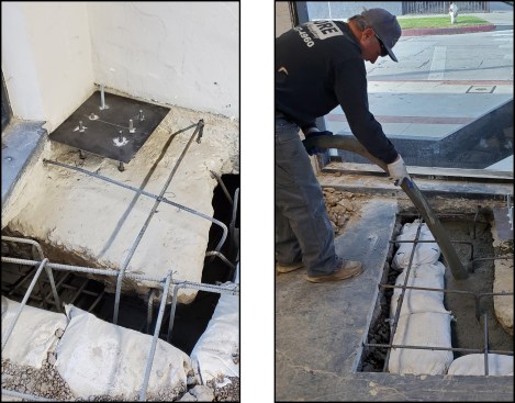
Underpinning the existing footings. Starting out, we needed to increase the size and bearing capacity of the footings under the two concrete pillars supporting the existing lintel in the corners of the showroom’s end wall. We dug under the existing footings to create 4-foot-square by 24-inch-deep footings centered on the new W14x159 columns. The existing south footing was 18 inches deep, while the existing north footing was 14 inches deep. We needed to provide a minimum 16-inch-high work area under the existing footings, which resulted in roughly 34- and 30-inch-deep footings for the south and north locations, respectively. Using hammer drills and chipping guns, we first dug access pits alongside the footings so we could lay on our sides or crouch to dig out the clay soil from under the footings.
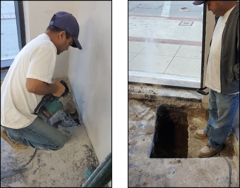
Moment frame. A crew member begins work accessing the existing north footing (left). Access pits were dug alongside the footings in order to remove soil from under the footings (right).
Before excavating horizontally under the footings, we needed to keep them from collapsing in the hole we were digging. The engineer recommended using sacrificial bottle jacks (a technique that was validated by a house mover I discussed the project with). Based on the load and the bearing values of the soil, the engineer’s detail called for six 12-ton jacks under each pad. To compensate for uneven soil, we dug out some soil, made a 4–inch-deep form, placed rebar in it, used rapid-set high-strength concrete, and troweled it smooth. We then set the jack on that. To compensate for the uneven bottom of the existing footing, we made a self-hardening modeling-clay dam around the perimeter of a 12×12 steel plate and poured a small pond of rapid-set high-strength grout in the center. Next, we placed the plate on the jack and jacked it up. Once the grout hardened, we jacked it tight. Then we were back to lying on our sides and digging (with horizontal digging, gravity doesn’t help push the hammer drill into the soil, so we got our exercise).
With excavation complete on both footings, we drilled six holes through the existing pads at each column for the footing-to-column connection. In the holes, we inserted 3/4-inch-diameter F1554 GR36 threaded rod, long enough to be embedded in the new concrete below the existing footing. Working from inside the access pits, we installed double-nutted square bearing plates on the threaded rod to resist pull-out forces. Then, #6 rebar was fished between the bottle jacks and threaded anchor bolts and set on stand-offs to make a grid.
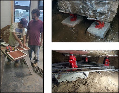
Moment frame. “Sacrificial” bottle jacks are used to support the existing footing during footing underpinning. To compensate for uneven soil, the jacks were set on reinforced concrete pads made with rapid-set high-strength concrete (top right). To compensate for the uneven bottom of the existing footing, a self-hardening modeling-clay “dam” was installed around the perimeter of a 12×12 steel plate (left), then a small pond of rapid-set high-strength grout was poured in the center. #6 rebar was fished between the bottle jacks and threaded anchor bolts and set on stand-offs to make a grid (bottom right).
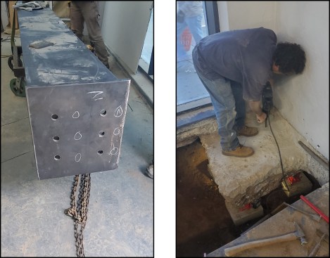
Moment frame. The columns arrived on site with 3/4‑inch steel plates welded to the base (left). Holes at anchor bolt locations were drilled into the existing footing; anchor bolts were long enough to be embedded in the new concrete below the existing footing (right).
Moment frame. A 1/8-inch-thick steel template (made to correspond to the steel bottom plate) is used to lay out the drilled anchor bolt locations (left). The template holds the all-thread bolts in alignment during the concrete pour (right).
After the engineer and building inspector blessed our work, we turned to filling the access pits with plastic sand bags filled with the excavated clay soil and embarked on pumping in the first of two concrete pours.
Erecting the steel. The steel fabricators showed up with their crane and the W12x136 steel beam and W14x159 columns. They craned the steel onto heavy-duty dollies and muscled the I-beams into the showroom through a nearby side door (there’s nothing quite like seeing a 6,000-pound-plus steel beam swinging over parked cars to get the blood flowing).
To make room for the steel brackets that the chain hoists hung from, we had to cut out some of the blocking we had installed earlier. The chain hoist gears whirred as the steel columns were dragged slowly up into place and lowered onto the all-thread bolts. The fabricators then plumbed the W14x159s with lasers.
While the fabricators were in the midst of installing the columns, our crew bolted a 4-by nailer to the top flange of the W12x136 beam. We later connected the rafter ends to the 4-by nailer with 2-by blocking and Simpson LTP4 clips and Simpson A35 framing clips that were nailed to the rafters and screwed to the roof decking.
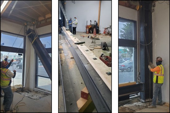
Moment frame. The W14x159 column at the south end is hoisted into place (left). A 4-by nailer is bolted to the top flange of the W12x136 beam; the nailer is needed to bond the roof diaphragm to the moment frame (middle). With the W14x159 column at the north end installed, the W12x136 beam begins its ascent (right).
Raising the beam, the fabricators worked one chain hoist at a time, switching from end to end as the beam inched skyward until it was high enough for us to weld the steel beam to the columns. Temporary shoring columns were continuously tightened, to act as a fail-safe measure, as the beam was raised into place.
Full-penetration welding (as specified by the engineer’s plans) to marry the beam to the columns ensued under the deputy welding inspector’s watchful eyes. Rapid-set grout was packed under the 3/4‑inch steel bottom plates at both columns and the moment frame was essentially completed.
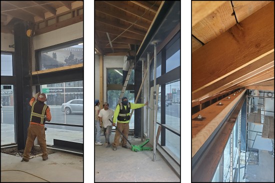
Moment frame. The W12x136 beam is hoisted into place with chain hoists hung from steel brackets (left). Temporary shoring columns are continuously tightened as the beam is raised into place (middle). With the beam set and welded, the 4-by nailer bolted to the beam is ready for 2-by blocking and metal clips (right).
Steel lintel. With the inspection completed, an 8x8x1/2-inch steel angle was welded to the moment frame by the fabricators and later fastened to the existing Z-shaped concrete lintel. The point of this exercise was to bond the concrete lintel to the moment frame to resist sideways motion commonly found in earthquakes, and prevent its collapse. Previously, I had the lintel radared and the buried rebar located and marked so when we drilled out and installed the new anchors (5/8-inch-diameter GR36 threaded rod at 24 inches on-center set in epoxy), we wouldn’t hit buried rebar and potentially weaken the lintel.
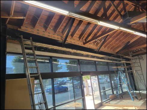
Roof connections. Completed structural work at the angled, wall-to-wall storefront opening includes the steel angle lintel, steel angle …
… diagonal bracing, 2-by blocking, and metal connectors.
Finishing up. Now it was time for the second concrete pour, which buried the column base plates. The finisher troweled the pour smooth. It’s an impressive thing of beauty, this moment frame consisting of three massive sticks of steel, yet it tucks into the showroom unobtrusively.
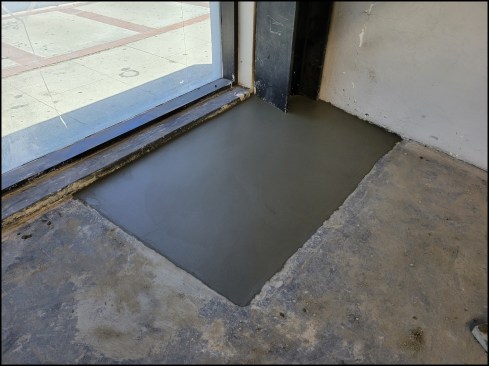
Moment frame. A second concrete pour buries the column base plates and is troweled smooth.
Photos by Gerret Wikoff, illustrations by Tim Healey