Beams are the horizontal supports used throughout a structure to carry and transfer loads across wall openings and floor and roof spans. While individual joists, rafters, and trusses also function as beams, I want to concentrate your attention in this article on headers and beams that carry distributed loads, such as tributary floor loads or bearing walls. (See “Structural Design Basics,” Oct/21, for an introduction to simple supported beams and tributary loads.)
Related Articles
In This Series:
Structural Design Basics
Beam Stress and Strains: A Lesson in Statics
Practical Engineering articles:
Calculating Loads on Beams and Headers
Sizing Engineered Beams
Engineers refer to beams as “flexural” members: In other words, beams bend. We can’t avoid their bending; we just don’t want beams to bend too much. In fact, this tendency to bend, or elasticity, is essential to a beam’s strength. Materials without elasticity are brittle and subject to shattering—the sort of sudden and catastrophic failure we’d prefer not to have in a structure. Better that the structure be able to absorb some of the force, which causes the beam to deform, or bend into a curved shape. This deformation is normal as long as the loads are limited and the beam returns to straight once the load is removed. But when it bends too far, the deformation will set—it sags and won’t bounce back. Sagging is itself a failure, but it’s better than shattering, and we can limit such a permanent deformation by understanding the elastic constraints of structural materials.
A beam (an early Old English word for tree; “baum” in German and “boom” in Dutch, which also survives in modern English as a type of beam common to cranes, lifts, and sailboats) is governed by five principal factors that engineers must account for when designing a structure: the beam’s material, length, load, and cross section, as well as the configuration of the building elements that support the beam. I am going to focus this discussion on rectangular wood beams that are supported at each end (a “simply supported beam”), but by the end of this article, you should have an appreciation for how each of these factors plays a role in the beam’s strength.
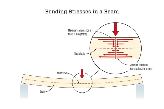
When a beam bends, the fibers along the top edge are squeezed, or compressed, together. At the center of the beam, the direction of stress reverses. Below this, the fibers are stretched, and the distance they are stretched reaches a maximum tension stress along the bottom edge. At the point where the bending stresses reverse direction, the longitudinal stress is zero. This point lies along the neutral axis of the beam, which lies at the center of gravity.
Stress and Strain
Let’s start with a few key terms:
Stress. In popular language, stress (the physical sort, not the emotional or mental kind) is a force exerted on a material, and this force causes the material to deflect. Even if you can’t tell that a concrete foundation deflects when you walk along a sill plate, there is a reaction force. As J.E. Gordon put it in Structures: Or Why Things Don’t Fall Down, “When you climb the tower of a cathedral it becomes shorter, as a result of your added weight, by a very, very tiny amount, but it really does become shorter.”
In a strict sense, stress specifically refers to an internal force in a material that resists an external force. This idea was first applied to structures by Robert Hooke, though a lot of folks today tend to know it as Isaac Newton’s third law of motion: For every action, there is an equal and opposite reaction. This is an essential concept in statics. Think of a force, such as a weight, pushing straight down on a beam that is supported at each end; there is an upward reaction equal to half the total downward force at each end of the beam. The reaction forces are smaller at each end of the beam, but together they balance the total load pushing down on the beam.
We don’t want motion in buildings, we want balance. For all the weight of the building plus snow and wind exerting loads on a beam, we want the fibers in the beam to resist the load without excessive deflection. Some of the force will be absorbed in the beam, causing it to bend, but the majority will transfer to the ends, where we want the foundation supporting the ends of the beam to resist the forces, transferring them to the earth, which we want to stay put for as long as the building stands.
Figuratively, we can think of this balance as a game of push hands: If you push against a person with a certain force and they push back with the same amount of force, you both stand still. That’s the way we want our buildings to stand. Do the fibers in the beam, or the foundation or the earth push back? Well, yes, they actually do. Zoom in on the stresses in the beam and imagine the molecules that comprise the beam’s fibers. As the beam flexes downward, the fibers on top are shortened; they get pushed together or compressed (see illustration “Bending Stresses in a Beam,” at top). The fiber molecules near the top of the beam are squeezed, and as when the positive poles of two magnets are pushed together, the atoms in those molecules resist changing the distance between the electrons and the nucleus, and do, in fact, push back with force. Similarly, the molecules in the fibers that are stretched in tension along the bottom of the beam are pulled apart. Their reaction is to pull inward because of the attraction of particles. Hooke didn’t know as much as we do about the laws of chemistry; he described the effects, which he witnessed by testing different materials under load, as analogous to springs that pushed and pulled to create the reaction forces he observed, but he was definitely onto something.
Strain. Beams are not held in perfect static equilibrium. They move. (Remember that tiny, tiny movement that shortens the cathedral tower?) The amount of that movement is strain—the measure of deformation that occurs in a material under stress. For the fibers along a beam, which is subject to a load pushing straight down, the strain is defined mathematically as the change in length (after the beam is squeezed at the top or stretched at the bottom) divided by the original distance (the length of the beam before applying a load).
Hooke’s brilliance was that he related stress and strain, articulating what is known as Hooke’s law: For every stress, there is a proportional strain. Or, put another way, the amount of deformation of an elastic material is proportional to the stress applied to it.
Hooke was thinking in terms of whole structures and his theories didn’t always hold up perfectly to testing. But a couple of hundred years after Hooke, the English physicist Thomas Young took the concept further to arrive at a method of calculating the ratio of stress to strain at a given cross section through any material. (In a wood beam, this cross section is a rectangle.) His formula, Stress/Strain = E, is known as Young’s modulus, or the modulus of elasticity (“modulus” means “ratio”).
If you plot stress to strain on a graph (see below), the values form a straight line in the region where Hooke’s law applies (where they are directly proportional and the material remains elastic). The material remains elastic so long as it returns to its original shape when the stress is removed (strain = 0). This region where Hooke’s law applies is commonly referred to as the allowable stress, since no permanent deformation occurs. For example, the beam supporting a floor might deflect when you walk across it, but it doesn’t remain in a sagging position when your weight is removed.
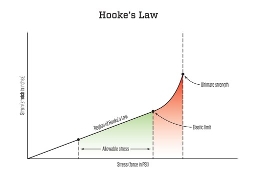
As stress increases, a material reaches its elastic limit. This is above the allowable stress and overloads the beam. As the stress increases above this limit, the strain increases at a geometrically greater rate relative to the stress. This pushes the fibers in the beam beyond their ability to recover their original shape, and the deformation becomes permanent (for example, the sag remains). If the stress increases even more, the material reaches a point where it reaches ultimate strength—the point where strain increases without limit: The beam breaks.
Every material has a definable modulus of elasticity (E). Each wood species has a different E, and most carpenters have a good sense for this: An oak beam is stiffer than a spruce beam, and so forth. E is not typically something engineers calculate, though they could; they look it up in the Wood Handbook or in the American Wood Council’s National Design Specification.
Bending Strength
E is a measure of stiffness, not strength. The bending strength of a wood beam depends on a combination of factors:
First, think of the compression stresses in the top of the beam and tension stresses in the bottom. These are the reactions to the force applied to the beam, and when you have these reactions—these tendencies to move in different directions—separated by a distance, you have a moment arm (in essence, a teeter-totter). As a load is applied to the beam and the bending stresses increase, there is a tendency for the teeter-totter to move or, rather, for the beam to rotate around the neutral axis, which in this circumstance is also known as the axis of rotation.
The bending moment can be calculated at any section of a beam using a distance (y) from the neutral axis. This moment is also a function of the load and the span of a beam (L). If the reaction stresses within a beam remain in equilibrium, the beam holds together. But if a beam’s resistance to tension falls short of its resistance to compression (or vice versa), the rotational force will tear the beam apart.
The concept of a moment at a given beam section is important because it tells us a lot about the strength of a beam: The strength comes from holding the two edges together (the two areas where the bending stresses are highest) to maintain equilibrium. But the distance between those stress areas—the web that holds the top and bottom flanges of a wood I-joist or a steel I-beam together—is governed by shear, which we’ll discuss below. Because the bending stresses are minimal in this middle area, this part of the beam can be slimmed down quite a bit (or punctured by holes or have the highest proportion of and largest knots) relative to the top and bottom edges.
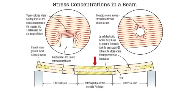
The lines running along this beam in the inset views represent longitudinal stresses. Whenever these run into a notch or a hole, the stresses become concentrated around the edges of the cutout. The concentration is acute at corners and more gradual around curves. Because the bending stresses are greatest at the edges of a beam, it becomes immediately apparent why we want to place large holes and cutouts close to the neutral axis (and preferably in the middle of the beam section). Knots and waney edges create similar stress concentrations, which is why lumber is graded to limit such defects.
Second, bending strength has a geometric element. We know that a joist held on edge is stronger than a plank of the same lumber dimensions lying on its face. This element is called the section modulus, or S—a relation of depth to the width. (The equation is not a direct proportion.)
Third, bending strength depends on the strength of the wood fibers in a beam. This is a property—extreme fiber stress in bending (designated Fb)—that varies by wood species. Stronger woods will have a greater Fb.
To evaluate the bending strength of a beam, we can combine these three factors into the equation: M = Fb x S. When M is equal to Fb x S, the beam will break. As long as M is a lower number than Fb x S, the beam is strong enough to bear the load.
When engineers design a beam, they know M by calculating a maximum bending moment from the unit load on the beam and the span. They then solve for an actual bending stress (fb) to see if the load limits match the proposed Fb for a beam of a certain species.
Shear Strength
Bending strength is only one value engineers look at when designing a beam. They also evaluate shear. Most of us are inclined to envision something like a pair of metal shears slicing through a piece of galvanized flashing. This applies, but the focus is on the two edges of the shears sliding by each other with force that shears off the metal between them. The word “shear” refers to the stress in a material that causes one part to slide past another part in a parallel plane. It’s often applied to a rock face, when one layer of rock fractures and slides past another. This same stress can act on a beam. Breaking a stick for campfire wood, either pulling it across your knee or leaning it against a rock and stomping on it, is a familiar example of applying shear stress when the break results in a split down the center. Horizontal shear failure in beams typically occurs in the same fashion along the center line.

Bending stresses (at left) act perpendicular to the cross section of a beam, and include both compression stresses (at the top of the beam) and tension stresses (at the bottom). This view shows how those stresses are distributed across a beam section. In a symmetrical cross section (such as the rectangle of most wood beams), the center of gravity lies at the middle between the top and bottom edges.Shear stresses (at right) act parallel to the cross section. The maximum vertical shear stress occurs at the center of this section.
In designing a beam, we are concerned first with vertical shear stresses through the same section that bending stresses are evaluated. Vertical shear stresses work opposite to bending stresses. Not only do they act parallel to the beam section (running down from the applied force)—as opposed to bending stresses, which act perpendicular to the section—but the maximum vertical shear stress is greatest at the center of the section, precisely where the bending stresses are zero (see illustration “Bending Stress and Shear Stress,” above).
In our discussion of bending moment above, we noted that the bending stresses are lowest in the middle “web” section. The actual upward reaction that enables a beam to sustain a downward load comes from the shear strength of this web, the ability of the material holding the longitudinal wood fibers together. Shear stresses acting on a rectangular section create tension and compression stresses at a diagonal to the beam section (in essence, the shear reaction is racking the rectangular section). This is why OSB, which is strong in all directions, is used for I-joist webs, and why the web members in trusses are positioned at 45 degrees to the top and bottom chords.
Deflection
In the final appraisal of a beam, engineers also evaluate deflection. With floor beams especially (and floor joists and even floor sheathing when tile is going over it), they are often more concerned with deflection—the amount a beam will flex—than about failure in bending strength (breaking beams are rare). The calculation of maximum deflection—how much a beam will sag when the design load is placed on it—is one an engineer will make for all beams to ensure that the expected loads stay below the elastic limit, above which the beam will permanently sag. But carpenters should be able to measure the expected deflection to keep it within certain limits (see illustration, “Evaluating Deflection,” below).
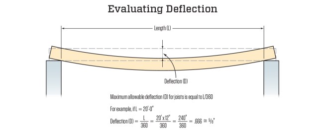
By code, the maximum deflection allowed under full load is the joist’s clear-span distance in inches (L) divided by 360. L/360 means that a 30-foot—or 360-inch—span can safely deflect 1 inch (360/360 = 1). At a span of 20 feet, as in this example, the deflection is 5/8 inch. (Illustration not to scale.)
L/360 is the maximum allowable deflection set by code. However, many feel L/360 is minimal and prefer to maintain at least L/480 (this would be 1/2 inch in the example shown in the illustration above). To control floor vibration (the bounciness that causes the dishes to rattle when you walk across a floor), Frank Woeste recommends sizing beams to a limit of L/600 (a little over 3/8 inch in our example) or limiting it even more, depending on the floor span, on-center spacing, and sheathing thickness (see “Controlling Floor Vibration,” Dec/15). And if large-format or stone tile is going over a wood floor, Michael Byrne recommends the floor members, including the sheathing spanning between joists, meet a maximum deflection of L/720 (a bit under 3/8 inch in the example above; see “Tiling Over Plywood Subfloors,” Mar/11).