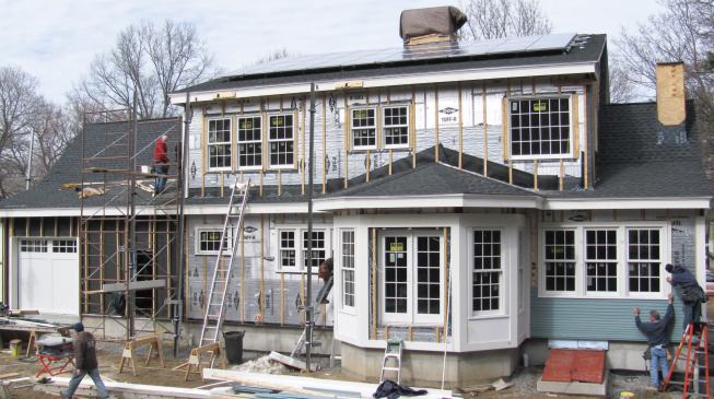
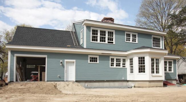
Editor’s note: This is the second installment of a
two-part story; “Building a High-Performance Shell”
ran in the May 2010 issue.
Our company focuses on energy- efficient retrofits and new
construction. Last month, I described the advanced framing and
foam-board sheathing that we used in building a new home in
Concord, Mass. The house was designed by architect Betsy Pettit
of Building Science Corp. for owners who wanted a sustainable
home with monthly energy costs that would remain fairly
constant from one season to the next. They also wanted a
building that was ahead of its time, so that 30 years from now,
should they decide to pass it on to their children or sell,
they wouldn’t be handing off a dinosaur. These goals
dovetailed perfectly with our own.
Windows and Doors
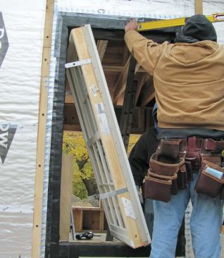
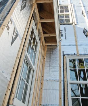
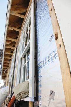
To terminate and seal the double layer of 2-inch foil-faced
Tuff-R polyiso board around the rough window openings, we lined
them with 1/2-inch plywood bucks that project 4 inches beyond
the framing. The thickness of the sheathing ruled out
installing the windows — Marvin Ultima aluminum-clad
low-E argon tri-pane double-hungs (888/537-7828,
marvin.com) — using
their vinyl nailing fins. Instead, we attached Simpson ST9
strap ties
(strongtie.com) to the
windows’ side jambs, two per side, with 1/2-inch wood
screws (see Figure 1). After adjusting for an
even gap around the jambs, we screwed the straps to the
framing. The straps have enough flex that we’d be able to
shim the jambs plumb later.
A.
B.
C.
D.
Figure 1. Metal strap ties screwed to the jambs secure
the windows to the framing (A). Exterior window casings were
fastened over the 1x3 siding vent strapping (B). The author
preassembled the window trim using composite lumber and PVC
subsills (C). Water that bypasses the siding and trim is shed
by the foam sheathing’s foil face (D).
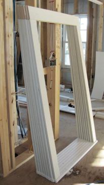
On the exterior, we added flat casings and subsill extensions,
made and installed as preassembled units. For all exterior
trim, we used TUF Board (800/452-2117,
tufboard.net), a
wood-PVC composite that doesn’t expand and contract
nearly as much as some of the solid cellular vinyl trim
we’ve tried. We used a complementary Azek molding under
the window sills. The window trim is simply butted around the
outside of the windows, installed over vertical strapping that
vents both the trim and siding (there’s more discussion
of the venting ahead). With the windows sealed against the
foil-faced sheathing, any water that gets past the trim and
siding will drain back out at the bottom of the wall. The
painters caulked the joints between the trim and the window
jambs but kept the bottom edges caulk-free for drainage.
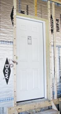
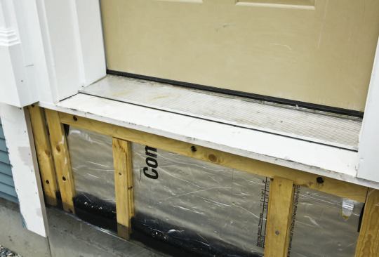
When installing the exterior doors, we aligned the outside edge
of the 5 9/16-inch jambs with the framing rather than with the
foam, creating a 4-inch inset. If we had used a deep extension
jamb on the interior, it would have prevented the doors from
fully opening. Instead, we ordered the doors without exterior
trim, applied exterior extension jambs and trim, and extended
the sill with TUF Board (Figure 2). Over the
rim joist below the door openings, we installed a single layer
of foam with a 2x8 ledger bolted above it for threshold
support. We then covered the ledger with 1/2-inch foam board
and installed a self-adhering flashing pan in the rough
opening.
Figure 2. To provide an unobstructed swing, exterior
doors were installed as if in a conventional 2x6 wall (left).
Exterior extensions to the jambs and threshold rely on
composite lumber and caulk (right).
Back-Vented Siding
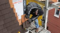
The prefinished WeatherBoard (800/233- 8990,
certainteed.com)
fiber-cement siding chosen for this project is installed over
vertical 1x3 strapping, installed at 24-inch centers over the
studs. This strapping creates a venting and drying space behind
the siding. The foam sheathing’s foil face sheds any
water that may be driven past the siding.
We screwed the strapping through the 4-inch-thick sheathing
using 6 1/2-inch HeadLok screws (800/518-3569,
fastenmaster.com). At
this length, the screws get a 2-inch bite into the studs.
Passing as they do through 4 inches of foam board, you might
expect them to eventually bend under the weight of the siding
and allow it to sag. In fact, though, we used the exact same
assembly on another job more than four years ago, and the
siding shows no signs of movement — so it appears to work
pretty well.
We started the strapping flush with the bottom edge of the
sheathing. Lengths of 41/2-inch-wide galvanized metal flashing,
overlapping the mudsill and foundation, protect the bottom edge
of the foam sheathing from UV degradation, bugs, and sparks. We
attached a continuous strip of nylon insect screen to the
flashing and let it hang until the strapping was installed
(Figure 3). We blocked between the strapping
with strips of Cobra plastic-matrix ridge-vent material
(973/628-3000, gaf.com), then
folded up the screen and tacked it to the strapping. The vent
material holds the screen against the back of the siding,
helping to keep bees and other bugs from nesting in the vent
space. To prevent the flashing from drooping, we screwed it to
the strapping ends.


Figure 3. The sheathing is strapped on 2-foot centers,
directly over the wall framing (left). The top of the venting
channels is open to the soffit, ensuring positive airflow from
the bottom up. Ridge-vent material blocks the gaps between
strapping, forcing an insect barrier screen against the back of
the siding (right).
Blocking for trim. At the two-stud outside corners,
the 4-inch offset created by the foam board places the
strapping conveniently behind the 1x8 corner boards without the
need for any supplemental blocking. We preassembled the corner
boards from the back using pocket screws and attached them to
the strapping with stainless steel trim-head screws.
The strapping installed over the studs on both sides of the
windows supports the window trim. But at inside corners and
around windows and doors, we needed additional strapping to
catch the ends of the siding. In these places, we installed 2x4
ladder blocking in the framing cavities and screwed the added
strapping to the blocks through the foam. Because the ladder
blocking is installed on the flat in the wall bays, it would
eventually be buried in blown-in cellulose insulation and
wouldn’t add greatly to the conductive heat loss.
Siding installation. The client wanted a particular
look for the siding, one typical of older Cape-style homes: The
courses start narrow at the base of the wall, with a 1 7/8-inch
exposure, and gradually widen over about 15 courses to the
standard 4 1/2-inch face (Figure 4). You
can’t effectively overlap 5 1/2-inch-wide fiber-cement
siding at those narrow exposures; it stacks up in a thick pile
on the wall. So we played with some mockups and found we had to
rip each course to maintain the 1 1/4-inch overlap prescribed
by the manufacturer — a dusty and time-consuming process.
The siding is blind-nailed in this overlap zone, which is
pretty tight. We discovered that if we nailed a little too
close to the top edge, the material tended to break out,
something we haven’t seen when installing Hardiplank. In
general, the thinner, less-expensive WeatherBoard required
gentler handling than we were used to during installation, and
I’m not inclined to choose it again.

Figure 4. The fiber-cement siding was custom-ripped to
allow narrower courses and tighter stacking at the base of the
wall.
We painted both the trim and the siding with two coats of
acrylic latex. The vented installation will help ensure a
long-lasting, low-maintenance finish.
Air-Sealing and Insulation
To insulate the walls, ceilings, and roof, we used a
combination of foam board, spray-foam, and cellulose. Our
general goal was to achieve R-values of 45 for the walls and 65
for the level and sloped ceiling areas. In the basement, which
would be finished, we insulated the walls to R-25 and installed
2-inch R-10 XPS foam under the slab.

The asphalt-shingled roof is conventionally vented at the
ridge, the Cobra vent balanced with aluminum strip vent in the
soffits. For vent baffles at the eaves and in sloped ceiling
areas, we used 2-inch R-13 foam board, spaced down from the
underside of the roof sheathing with 2-inch foam spacers
(Figure 5). We glued the spacers to the
sheathing and tacked the board over them, running it to a point
about 1 foot higher than the 16 inches of cellulose to be
placed in the attic. The eaves baffles are air-sealed against
the 2x12 rafters and top plate with a 3-inch layer of spray
foam. Over the baffles in the sloped ceiling areas, we sprayed
7 inches of closed-cell foam with a nominal value of R-45; we
then installed 2-inch foam board over the rafters. The combined
values of the board and spray foam results in a total R-value
of around 70.
A.
B.C.
D.
Figure 5. Foam-board vent baffles prevent wind-washing
of the cellulose insulation in the attic ceiling areas (A). A
3-inch layer of spray foam effectively air-seals the vent
baffles against the framing and insulates the rim joists to
about R-18 (B). Sloped ceiling rafter bays were fully baffled
with 2-inch foam board, then filled with closed-cell foam (C).
Note the insulated rim joist and squash blocks below the single
top plate. A layer of 2-inch R-13 foam board completes the
sloped ceiling insulation, yielding a total approximate R-value
of 70 (D).
We also used closed-cell foam to insulate and seal all rim
joists, the sloped ceiling areas, and the two doghouse dormers
(Figure 6). A 3-inch layer of foam at the rims
has an R-value of about 18 and provides additional air-sealing
at this typically leaky junction.
A.
B.C.
D.
Figure 6. Complex framing areas are ideal spray-foam
candidates (A). At roughly R-6 per inch, the 2x8 framing bays
approach a nominal R-44. Two doghouse dormers were also
insulated with closed-cell foam (B). The finished basement
walls were insulated to R-25 with a combination of 2-inch XPS
foam and R-15 fiberglass batts (C). Note the air-sealing tape
over the seams. Spray foam on the rim joist laps onto the XPS
on the foundation walls, creating an air seal along the top of
the board (D).
Basement walls. In the basement we installed 2-inch
XPS foam on the foundation walls, overlapping it at the top
with the closed-cell foam insulating the rims. We framed 2x4
walls in front of the foam and insulated them with fiberglass
batts instead of cellulose. We did this because basement
flooding is common in the area; if a flood overwhelms the
subslab drainage and sump pump, the insulation will drain and
dry to the interior without settling. In fact, in an effort to
keep things dry, we installed the foundation with its top about
3 feet above finished grade, placing the slab a few inches
above the average water table.
Even though the foam sheathing was taped at every seam in both
layers and sealed to the framing with adhesive caulk, we still
didn’t consider it a fully effective air seal. Before
blowing in the cellulose, we worked on sealing the framing from
the interior, caulking every seam that might constitute an air
leak in the shell (Figure 7). This proved to
be an extensive and expensive undertaking. We used acrylic
latex caulk on every joint between double framing members in
the exterior walls. We’d put a generous bead of subfloor
adhesive under the bottom plates before standing the walls, but
you can’t visually check for voids or gaps, so we went
ahead and caulked all seams between the bottom plate and
subfloor. In the basement, we caulked where the 2-inch XPS foam
on the foundation walls met the slab, and we sealed the seams
with WeatherMate tape (866/583-2583,
building.dow.com). We
spent about $800 on caulk and more than $8,000 in labor over
two weeks, during which time someone from Building Science
Corp. periodically came out and identified still more areas
that could be caulked.


Figure 7. Leaving little to chance, the crew caulked
all seams between framing members and subfloor (top). Foam
backer rod, sealed with caulk, was used in lieu of expanding
foam around window and door jambs (bottom left). Window sealing
was time-consuming, with caulk outlining the metal installation
straps and the interior edges of the self-adhering window
flashing (bottom right).
The air-sealing effort also included a labor-intensive
treatment around all the windows and doors. We avoided using
expanding foam around the jambs, not because it doesn’t
seal well, but because it too thoroughly fills the gap. If
water were to get past the jamb, it could remain trapped and
lead to rot. Instead, we inserted foam backer rod around the
jambs, pressing it just beyond the interior edge, then capped
it with caulk. This way, any water that gets in still has a
chance to dry to the outside, where the underside of the sill
is caulk-free and can drain. We caulked around the metal
tie-straps, too, and along the edges of the self-adhering
membrane protecting the rough openings.
Insulation
The 2x6 wall bays were insulated with dense-pack cellulose,
blown in behind a permeable plastic membrane. To support the
cellulose in the attic spaces, we had to hang those ceilings
first, using stiffer, 5/8-inch drywall to avoid a
“quilting” effect over the 24-inch framing centers
(Figure 8). After hanging the board, we
checked from above for light leakage through seams and
fixtures, and caulked them all tight. We also caulked the
perimeter of the drywall to the top plates, from below.
Figure 8. Dense-pack cellulose insulation was blown
behind a permeable membrane stapled to the studs (top). Attic
ceiling areas were sheetrocked first to support the insulation.
Attics received a 16-inch layer of loose-fill cellulose with an
R-value of 65 (bottom).
Against the architect’s recommendation, the homeowners
insisted on having recessed lighting in the ceilings. Despite
their ICF housings, the fixtures weren’t airtight, so we
covered them from above with expanding foam. Hopefully, the
homeowners will use compact fluorescent bulbs to help prevent
the cans from overheating and tripping the thermal
breaker.
We performed a blower-door and smoke test before installing the
cellulose. Even at this intermediate stage, the result —
1.37 air changes per hour at a pressure of 50 pascals (ACH50)
— easily met the 1.5 ACH50 we’d targeted as our
goal for the finished home. We identified a few leaks along the
top plate where air found its way between the sheathing and the
framing, and applied more caulking to seal these areas.
In retrospect, I believe that rather than putting all that time
and caulk into air-sealing, it would have been more economical
to have had every wall bay “picture-framed” between
the sheathing and the framing with closed-cell spray foam. Our
insulation contractor estimates that this would have added
$1,500 to the job cost, but it would have significantly reduced
our labor.
Drywall
With two-stud corners and backerless wall intersections, we
used drywall clips instead of nailers to support drywall
corners (Figure 9). Both the hangers and I
were surprised at how easy the clips were to use. Their purpose
is threefold: First, they reduce lumber usage; second, without
a nailer in the way, areas above the top plates and behind wall
tees and corners are easier to insulate; and third, they help
prevent drywall cracks in the corners where wood movement can
otherwise introduce stresses. Cracks aren’t just
unsightly; they also can contribute to air leakage through the
wall assembly.
Figure 9. Drywall clips replace lumber backers in wall
and ceiling corners.
The blueboard and skim-coat plaster serve as the primary
barrier to air movement through the walls and ceiling. When
hanging the sheets, we ran a bead of acrylic caulk at all top
and bottom plates, at wall ends, and around all openings,
fixtures, and electrical boxes. At drywall clip corners, we
simply caulked the vertical seams after installing the board
— good insurance should the plaster crack in the corners
despite the clips.
Mechanical Systems
This home is heated by forced hot air, with the ducts sized for
air conditioning and installed entirely in conditioned space.
The furnace is a natural gas-fired Evolution System Plus 95s
(800/428-4326, bryant.com) with up to 95 percent AFUE. Instead
of installing a cooling-only unit, we used a heat pump that can
supply both cooling and heating. It provides heat at
temperatures of 35°F and above, relieving the
furnace and saving some fuel. A Fantech VHR 1404 (800/747-1762,
fantech.net) heat-recovery
ventilator delivers the home’s makeup air supply. Both
the furnace and the Rinnai RC98HP on-demand water heater
(800/621-9419, rinnai.us)
are sealed combustion units.
Although the cooling load for the house was calculated at 1 1/2
tons, a 2 1/2-ton 18 SEER unit was the smallest available.
It’s possible this could lead to short-cycling of the
system; that remains to be seen. Presumably, as tight-home
construction becomes more common, smaller systems will,
too.
Solar power. On the roof, a 7-kilowatt photovoltaic
array of 230-watt OnEnergy panels (800/237-4277,
sharpusa.com) helps
offset electrical usage, with excess power generation being fed
back into the grid (Figure 10).
Figure 10. A 7-kW PV array on the shed-dormer roof is
projected to supply more than 100 percent of the home’s
electrical consumption (left). A digital electric meter
displays a constant readout of power delivered to and from the
grid (right).
Home Performance
Effectively air-sealing a home is a tall order, but redundant
taping and caulking of seams — along with careful
attention to detail — clearly paid off in our preliminary
test results. This was confirmed by the blower-door test we did
after completing the interior: We achieved .72 ACH50 —
nearly 50 percent lower (and better) than the outcome of our
preliminary test. Our focus throughout the job on energy and
resource conservation has already helped place the home well
above the 100 mark required for a LEED Platinum
designation.
More important, our efforts will pay back in the home’s
overall efficiency and performance. Whenever there’s
leeway in a construction budget, I push for higher levels of
insulation. Done properly, it’s one investment that can
pay for itself fairly quickly and, over time, continue to
reduce operating costs.
David Joyce owns Synergy Companies Construction in
Lancaster, Mass.