More About Scribing
Scribing Basics
Scribing Wood to Stone
Scribing Cabinets
Scribing the Final Floorboard
Lessons in Scribing
Fitting Post to Stone, Teriyaki Style
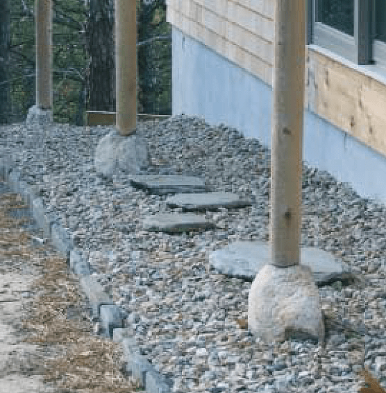
On a recent project, my crew and I incorporated a number of traditional Japanese building features, including a series of turned, structural cedar posts bearing on natural fieldstone footings. The posts support a wide roof overhang, which sheds its runoff directly onto a “moat” of 3/4-inch crushed stone that wraps the building’s perimeter between the foundation and the drip line (see photo below).
The footing stones appear to “float” in the gravel bed but are actually embedded in concrete on top of conventional, 10-inch-diameter sonotube piers that terminated just below finished grade. We stood the sonotubes on Bigfoot bases (F&S Manufacturing, 800/934-0393, www.bigfootsystems.com) to ensure good distribution of the admittedly minor point loads they’d be supporting. But the $14 Bigfoot form makes it simple to excavate for, support, and center each tube precisely on layout, an otherwise fussy, time-consuming task.
Irregular Logic
To secure the stones to the concrete piers, we drilled a 1/2-inch-diameter hole in each stone, tapped in a steel pin, and inverted the stone, embedding the pin in the wet concrete (see illustration, below).
The challenge we faced on this detail was how to accurately scribe the ends of the 4- to 5-inch-diameter posts to fit the irregular stone footings. What I needed was one of those banded, multifingered molding copiers, but one flexible enough to wrap around a post. I’ve never seen one of those, but, working in pseudo-Japanese mode as I was, I figured a handful of bamboo teriyaki skewers might do the trick.

The diameter of each post varied, as did the shape of each stone. And, because we had to fit the posts between two fixed and unmovable points (roof and rock), I decided that the surest method would be to cut a short length from the post at each location and make a custom pattern for each of the stones. I plumbed the cutoff atop the stone, using a bit of modeling clay to steady the piece. I located the line points for the scribe by sticking the skewers, one at a time, onto parallel rows of double-stick tape wrapped around the post. To secure this mini-palisade, I then wrapped packing tape around the outside and slit it vertically to unpeel the skewer pattern from the post (see photos, left).
After hollowing the end of the sample post with a wide spade drill bit, I used a jigsaw to cut to the scribe line. Then I began fine-tuning, rubbing chalk onto the stone to reveal and transfer the high points to the post end. I hogged out some of the waste using a cutter on a 4-inch grinder and fine-tuned with a rotary rasp in my drill.
Once the pattern piece matched up nicely on the stone, I tacked it to the end of the full-length post to transfer its scribe line, using an ordinary pair of dividers. To fill and seal the crude recesses inside the final scribe, I packed a glob of thickened epoxy onto the end grain and planted the post on the stone.
The roof rafters rested on a dropped purlin, which allowed us to stand the post on the stone, a couple of degrees out of plumb, and mark its top end for a fit.
After cutting the post to its final length, we used a bottle jack to lift the purlin about 1/4 inch, just enough to let the post slip into place. Releasing the jack allowed the weight of the roof to press the post firmly into its epoxy bed on the stone.


