I can’t count the number of different ways I’ve fastened guard posts to deck framing. But I started paying a lot more attention to this important detail in 2005, when Virginia Tech researchers Frank Woeste and Joe Loferski and their team tested common post connection details used by deck builders (see “Strong Rail-Post Connections for Wooden Decks,” JLC, Feb/05). What they found is that most commonly used post connection details would not pass the minimum code requirement of a 200-pound load (plus a 2.5x safety factor to account for variations in field installation and degradation of the connections due to time and exposure to the elements). To strengthen this joint, the team devised and tested guard-post-to-frame connections using metal hardware that transferred outward force on the posts to the joists. After reading their article, I started using their tested connections right away.
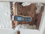
My decision to adopt tested assemblies using hardware instead of going with my carpenter’s notion of a strong connection was reinforced a few years later when I visited a deck we had built before that guard-post article was published. The owner asked me to look at the railing on his deck, which had been hit by a falling tree. Aside from the damage caused by the tree’s impact, I noticed that most of the 17 guard posts that we had carefully installed only seven years earlier now wobbled and deflected several inches with just a moderate push. Yikes!
Still, other than the 200-lb. load requirement, the 2000 through 2018 versions of the International Residential Code didn’t offer any guidance on guardrail-post fastening. Construction details were left to deck builders to design and assemble, and to code officials to approve or disapprove. That has changed in the 2021 IRC, which has a new section, “R507.10 Exterior guards,” that provides more guidance on the guard-post-to-frame attachment (see “Guards, Handrails, and the 2021 IRC,” by Glenn Mathewson, JLC, Nov/Dec/21).
In this article, I’ll explain two basic approaches to fastening posts to the deck framing and dive deeper into the “structural screw and block” approach that will satisfy the new code requirements. Most jurisdictions haven’t adopted the 2021 IRC yet, so now is a good time to prepare, by trying out different approaches for guardrail post connections that will comply with the new code section and seeing which construction details work best for you and your crew.
Know the Code
Section R507.10.1 in the 2021 IRC states, “Where guards are supported on deck framing, guard loads shall be transferred to the deck framing with a continuous load path to the deck joists.” Subsection R507.10.1.1 provides further detail: “Where guards are connected to the interior or exterior side of a deck joist or beam, the joist or beam shall be connected to the adjacent joists to prevent rotation of the joist or beam. Connections relying only on fasteners in end grain withdrawal are not permitted.”
In any guardrail system, the posts are the critical part of the load path that transfers loads applied to the guard system down to the deck frame. For either a site-built wood guardrail assembly or a manufactured guardrail system, where a post is fastened to a deck joist, the term “joist” in the code would apply to the joists at the ends of a deck, joists in the middle of the deck frame, and the rim joist (band joist) that fastens to the ends of joists along the front of a deck.
Note that the joist itself must be “connected to the adjacent joists to prevent rotation of the joist.” Essentially, that means that the joist to which a guard post is fastened must be reinforced to prevent that joist from twisting when someone pushes against the post. Think of the post as a lever. When a moderate force is applied against the top of the post, that force is amplified at the connection with the joist, potentially causing the joist to twist or rotate.
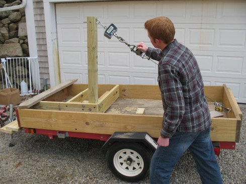
The author informally tested the strength of different guard-post-to-frame connections made with structural screws and blocking using a hand cable winch fitted with a 1,500-lb. digital crane scale.
The code doesn’t specify how to make the connection to prevent joist rotation. But it does prohibit connections that rely only on fasteners (nails and screws) driven into end grain, because it recognizes that they do not hold connections tight and are relatively easy to pull out. This is especially the case for deck frames, where the elements will take their toll over time and weaken connections that may initially feel solid.
So if you fasten posts to the rim joist, you also have to connect the rim joist to the adjacent joists (the deck joists that the rim joist is fastened to) in a manner other than driving screws or nails into the ends of those joists. The same would be the case for perpendicular blocking between the end joist and the next inboard floor joist. Fasteners that are driven through the joists and into the end grain of the blocks are subject to withdrawal; that’s why the code doesn’t allow us to rely solely on those fasteners.

The goal of the testing was to find out how well various screw-and-blocking deck post connection details would fare under the 500-lb. test load requirement of ASTM D7032, the standard that wood-plastic composite (WPC) guardrail systems have to meet to comply with code.
Two Approaches to Code-Compliant Connections
How to design and construct the connections between joists to prevent rotation can be puzzling. The code doesn’t want to limit our options, so it offers no prescriptive solutions, but on the other hand, how do we know that the connections we devise will meet the code? Ultimately, the decision is up to your local code official. I expect there will be a wide variation in how code officials apply this new section.
One way to be confident that your post-to-frame connection detail will meet code is to look to construction details that have had independent testing to demonstrate that they comply with code-required minimum load and safety factors. For example, the first set of tested post-to-frame connections that were developed by Virginia Tech researchers and published in JLC resulted in a detail that can now be found in the American Wood Council’s DCA6, Prescriptive Wood Deck Construction Guide. In addition, manufacturers of metal connectors and structural screws have researched post-to-frame connection designs and tested them to verify that those designs using their products will meet the same test requirements that manufacturers of wood-plastic composite (WPC) guardrail systems have to meet—a 500-lb. test load. That test load is based on a 200‑lb. concentrated guard load plus a 2.5 safety factor for tested assemblies and complies with the ASTM D7032 requirements noted in another section of the deck portion of the IRC.
Metal hardware. The original Virginia Tech post-to-frame connections relied on metal hardware to transfer loads on guard posts to the deck frame. By design, those details reinforce the joist that the guardrail posts are connected to and prevent the joist from rotating. I’ve used these details for years, but there were only a few basic connections. So I extrapolated additional connection details based on the principles Virginia Tech used in its designs (see “Code-Complaint Guardrail Posts,” PDB, May/11, and JLC, July/19). Though not independently tested, I believe that those designs meet the intent of the code: provide a continuous load path and prevent the rotation of the joist a guardrail post is fastened to.
One way to strengthen the connection between a guard post and the deck frame so that it will meet code is with specialized hardware, such as Simpson Strong-Tie's DTT2Z tension tie, but it's not the only way.
Blocking and screws. Another approach to securing guardrail posts to joists and securing the joists to adjacent ones to prevent rotation is using blocking and screws or bolts. Deck builders have been using blocking to reinforce guardrail posts for years.
But as the Virginia Tech research showed, common blocked post-to-frame connections weren’t solid enough. In some cases, the blocking or joists split out when a force was applied to the guard post, because fasteners were driven close to the ends of the wood, and in other cases, the fasteners driven into end grain pulled out. After seeing those failures, I didn’t think any arrangement of blocking and screws or bolts would be able to meet a 500-lb. test load, until a meeting with the FastenMaster tech team in 2013, where they demonstrated four post-to-deck-frame details using the company’s proprietary ThruLok structural screws that would meet a 500-lb. test load.
I started using the FastenMaster blocking details when installing guard posts on my deck builds right away. We were already installing blocking around posts to support notched deck boards and border boards, so it was easy to modify our approach to include these details.
What I learned from FastenMaster’s approach is that where the blocking is positioned and where the screws are installed make a big difference in how strong the connection is and how well it prevents the blocking and joists from splitting. And sometimes the blocking needs blocking. The elegant (though some may say awkward looking) feature of a couple of connection details is the use of a joist-height 4×4 block positioned behind the guardrail post. I’d always used 2-by blocking, but a single 2-by block can split when a force is applied and the fasteners are driven into the ends. The vertical 4×4 block works better—the screws penetrate side grain and the blocks are 3 1/2 inches rather than 1 1/2 inches wide.
A few years after FastenMaster demonstrated its block and screw details, Simpson Strong-Tie developed a series of tested block and screw connections using its SDWS structural screws that also exceed the 500-lb. test load. And I know of at least one other screw manufacturer that is doing block-and-screw connection design and testing of its own.
The new IRC requirements for exterior guardrail post connections don’t require that we use the details engineered by these screw manufacturers. You can devise your own connections as long as your local building inspector judges that you are preventing rotation of the joists that your posts are fastened to and that the connections aren’t relying solely on fasteners driven into end grain. But if your local official is looking for verification that the connections you use are in some way qualified by independent testing or designed by an engineer, then the designs that use proprietary screws and the manufacturers’ details should be acceptable.
Manufacturers don’t offer details for every guardrail-post-to-frame connection scenario you will encounter, however. For example, there are no designs for angled corners, inside corners, or the intersection of an end joist and the ledger. When you encounter a post location that doesn’t have a tested solution, you can follow the principles these companies use—moving the main reinforcing blocking behind the post, reinforcing primary blocking with secondary blocking that is side-fastened to the deck joists, and doubling up blocks—to design a custom detail.
Details You Can Use
Each manufacturer has its own variations on guardrail-post-to-frame connections. If you are counting on the strength capacity that the manufacturers achieved in their testing, then it’s important to carefully follow the installation guide published by the maker of the fasteners you’re using. Install the blocking as each detail in the instructions depicts, install the fasteners in the locations shown, and use the model and length of the fasteners called for at each location.
Outside corner post. It would seem that the simplest and strongest connection of a guardrail post to a deck frame would be fastening the post to the inside face of an outside corner. Screws or bolts driven in through the post from the rim joist on one face and the end joist on the other would seem bulletproof. But the Virginia Tech testing showed that because the bolts or screws are so close to the ends of the joists, the wood split.
FastenMaster’s corner post detail is made with ThruLok and either LedgerLok or FlatLok structural screws and a pair of full-height 4×4 blocks. For connection details, see the drawing below.
Simpson Strong-Tie’s corner post detail is made with SDWS timber screws, a single 4×4 block, and a pair of full-height 2-by blocks between joists. For connection details, see the second drawing below.
One solution offered by FastenMaster is to screw short 4×4 blocks on each side behind the guardrail post . This moves the screws helping to transfer the load into the joists away from the ends of the joists, so there’s less chance of splitting when a force is applied.
Alternatively, Simpson Strong-Tie’s corner detail uses a combination of double blocks behind the post between the end joist and the first inboard floor joist, and a 4×4 block between the double blocking and the rim joist to achieve the same result—moving the fasteners that resist the load farther back from the ends of the joists.
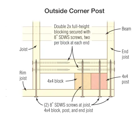
Pairs of screws driven through the rim and end joist into the joists and blocking are located 1 1/2 inches from the top and bottom edges. The two screws driven into the corner post are located 2 inches from the top and bottom edges of the rim joist.
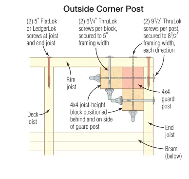
Where pairs of screws are required, the screws are located 1 3/4 inches from the top and bottom edge of the joists. Note: ThruLok screws are not recommended for saltwater locations; LedgerLok screws require 5/32-inch-diameter pilot holes.
Post along rim joist. Rim joists are commonly fastened to the ends of the deck joists with nails or screws. Because those fasteners are driven into end grain, the 2021 IRC specifically prohibits relying on them solely to prevent the rim joist from rotating and pulling away from the joists. The rim joist needs to be reinforced or the guardrail posts connected to the deck framing in a way that doesn’t rely on the rim joist (or both). Both designs use joist-depth blocking behind the guardrail post and between the joists.
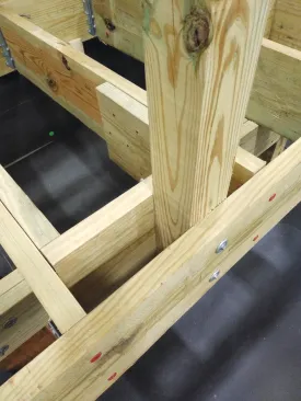
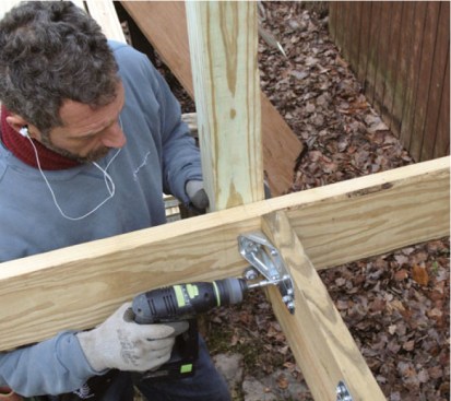
When fastening a post to a rim joist with FastenMaster ThruLoks, reinforce the connection with blocking as shown in the photo and in the drawing below.
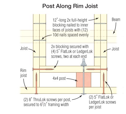
When fastening a post to a rim joist with FastenMaster ThruLok screws, the ThruLoks should be located 2 1/4 inches from the top and bottom edges of the rim joist, as shown. Either FlatLok or LedgerLok screws can be used for the framing connections; they should be located 1 3/4 inches from the framing edges.
FastenMaster reinforces a single 2-by block with blocks sistered alongside the joists. The guard post is fastened between the rim joist and the perpendicular block.
Simpson Strong-Tie uses double 2-by blocking behind the guardrail post and between the deck joists. In both details, the rim joist is fastened to the joists on either side of the post with structural screws. The guardrail post can be installed anywhere within the joist bay.
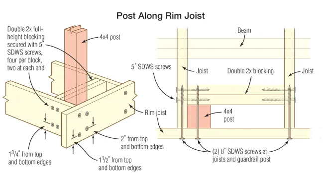
A post fastened to a rim joist with Simpson Strong-Tie SDWS screws can be located anywhere within the joist bay, as long as the connection is reinforced with blocking as shown in the drawings above. This detail requires 10 5-inch SDWS screws and six 8-inch SDWS screws, along with two lengths of full-height blocking between joists.
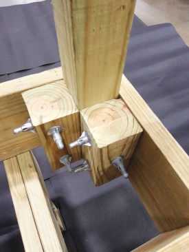
Post along end joist. End joists rotate easily without reinforcement. Both FastenMaster and Simpson use the same blocking arrangement: joist-depth 2-by blocks on either side of the guardrail post and between the end joist and the first inboard floor joist, along with a 4×4 vertical block behind the guardrail post and between the 2-by blocks. Screws fasten through the end joist, through the guardrail post, and into the 4×4 block, which is screwed through the 2-by blocks.
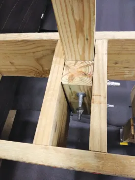
When fastening a post to an end joist with ThruLok screws, reinforce the connection with additional blocking as shown in the photo here, and in the drawing below.
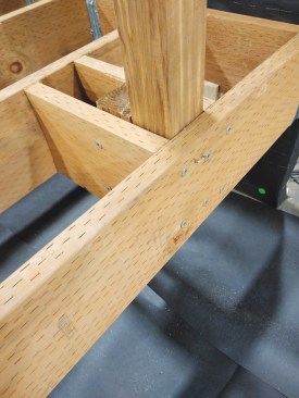
When fastening a post to an end joist with with 8-inch Simpson Strong-Tie SDWS screws, locate the post screws 2 inches from the top and bottom edges of the end joist, as shown in the photo above and in the second drawing below.
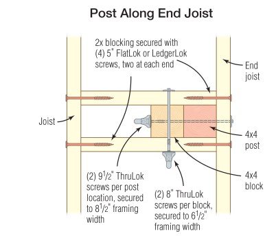
FlatLok or LedgerLok screws are used to fasten the blocking to the framing, as shown above. The ThruLoks are located 2 1/4 inches from the top and bottom edges of the end joist, and 1 3/4 inches from the top and bottom edges of the blocking.
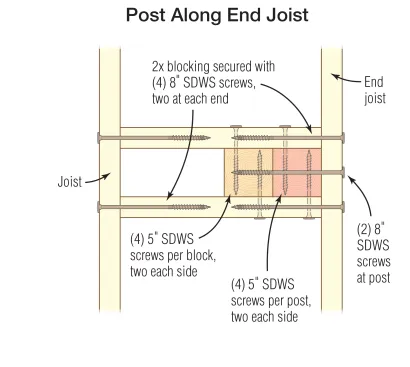
8-inch SDWS screws are used to connect the post and the blocking to the end joist, as shown above, with the screws driven through the end joist into the blocking 1 1/2 inches from the top and bottom edges of the joist. Pairs of 5-inch SDWS screws on both sides are also driven through the 2-by blocking into both the post and the 4×4 blocking.
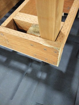
End joist at ledger. Neither FastenMaster nor Simpson Strong-Tie offers a detail for fastening a guardrail post where the end joist meets the ledger. One approach to secure the post is to drive screws through the side of the post and into the framing in the wall. But if there isn’t a stud or blocking in the wall, then you’re out of luck. I made up my own detail, mimicking the detail used farther along the end joist. The ledger takes the place of one of the perpendicular blocks between the end joist and first inboard floor joist. The short 4×4 block is screwed through from the block and into the ledger. While it’s not an independently tested detail, I believe that it meets the intent of the code.
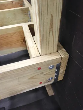
Where a corner post at the ledger can’t be screwed through the sheathing into wall framing, the author reinforces the connection of the end joist to the deck framing with blocking as shown above, and in the drawing below.
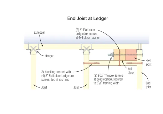
The author screws 2x and 4×4 blocking to the deck framing as shown above, then fastens the post to the end joist and 4×4 blocking with a pair of ThruLok screws.
Photos by Mike Guertin. Drawings by Tim Healey. ❖