[Editor’s note: This three-part series goes beyond code to offer a best-practices guide to deck ledger installation. In part one, we’ll take a close look at attachment details; later, we’ll cover moisture protection (Part 2) and lateral-load anchors (Part 3).]
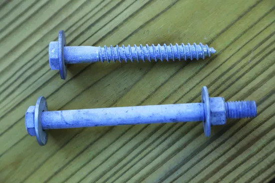
Hex-head 1/2-inch hot-dipped galvanized bolts and 1/2-inch lag screws with standard cut washers are the only two fastener options listed in the IRC for attaching deck ledgers.
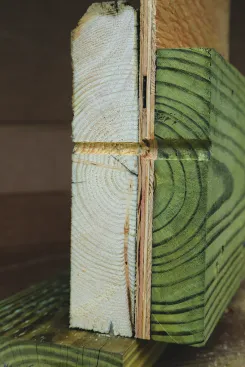
Deck ledgers are the odd duck of residential construction. Most gravity loads in platform framing rely on stacking building elements, such as joists and rafters on mudsills and plates, beams on posts, headers on jacks, and so on. Instead of stacking the load, however, deck ledgers rely on bolts or screws to transfer the live and dead loads of the deck into the frame of the house. Because of this, fasteners must be positioned accurately along the ledger and into the house rim joist at the spacing required by the building code or the fastener manufacturer’s instructions. Incorrectly positioned fasteners can split the ledger or the rim joist, and if the spacing isn’t matched to the joist span, there may not be enough fasteners to support the loads on the deck.
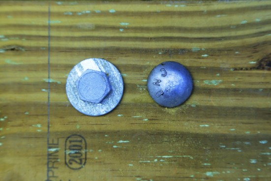
Carriage (cap head) bolts are not permitted fasteners. The cap-type head has 30% less surface area than a 1/2-inch bolt washer.
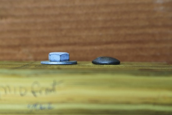
Cap head is thinner than a hex-head bolt.
Approved Fasteners
The International Residential Code lists two fasteners for directly attaching ledgers to a house: 1/2-inch-diameter hot-dip-galvanized hex-head machine bolts and 1/2-inch-diameter hot-dip-galvanized lag screws. Note that “carriage,” or “cap head,” bolts are not listed. The IRC also provides a table (R507.9.1.3(1)) for the spacing of the fasteners .
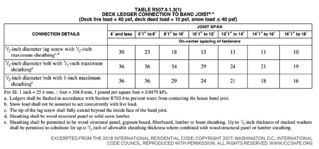
To determine fastener layout on a ledger, identify the joist span (listed in 2-foot increments) and the type of fastener. The joist span is measured from the center of the joist hanger at the ledger to the center of the beam the joists rest on and doesn’t include any cantilever overhangs past the beam.
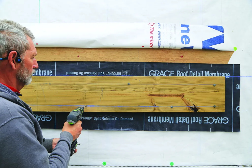
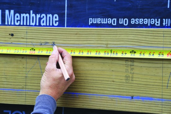
The bolts or lags must be placed along the ledger in two rows—one row along the top and one along the bottom—with the fasteners staggered between the two rows at the spacing indicated by the IRC table. For example, on a deck with a joist span of 15 feet, the lag screws are spaced 11 inches apart. To start the pattern, the first lag is placed on the bottom row approximately 3 inches in from the end of the ledger, and the next lag is located on the top row 11 inches from the first one. The next lag goes on the bottom row another 11 inches over, and the pattern repeats until the other end of the ledger is reached.
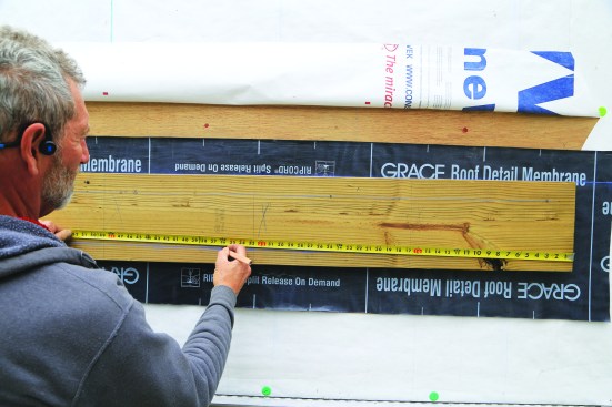
Fasteners are laid out on the ledger in two rows, starting approximately 3 inches in from one end, with the oncenter spacing from the code table staggered in a “W” pattern between the two rows.
Since bolt and lag heads can’t be countersunk into the ledger, the fastener can be moved left or right up to 3 inches to avoid conflicting with joist location or the hanger flange, provided the rest of the fasteners remain on the same layout.
Eventually, there will be conflict between a fastener head and a joist position (or the flange of a hanger supporting a joist). When this occurs, you are allowed to shift the fastener to the left or right up to 3 inches to avoid the conflict. Don’t be tempted to countersink a fastener head so that it is flush with the ledger surface—this is not permitted. Even when a fastener is shifted left or right, the spacing pattern of the remaining fasteners continues from the original layout point.
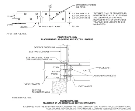
The IRC clearly spells out where the 1/2-inch-diameter lags or bolts should be located in both the ledger (top) and the rim joist (bottom).
Layout
To make sure the connection between the deck and house framing is structurally sound, the IRC spells out the orientation of the top and bottom fastener rows in the ledger and the house rim joist. Each one is simple on its own to understand, but when you combine the two and try to set the position of the ledger and maintain the minimum and maximum spacing of the two rows of fasteners, it can feel like a game of three-dimensional chess.
Applying the code figures when fastening a ledger can be confusing. The fastener locations through the ledger and through the rim joist differ, so you have to match the zones to ensure that the wood doesn’t split and that you provide enough support for the deck.
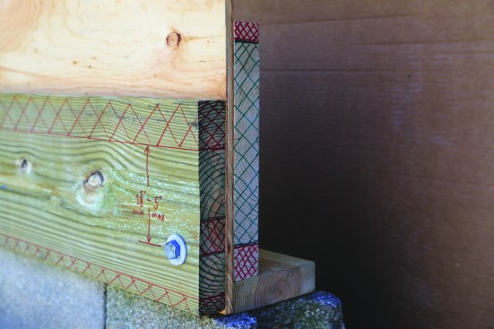
The limitations of the fastener row placement limit the level of the deck in relation to the inside floor level in the house. The deck’s elevation will also be influenced by the size of the house rim joist and the deck ledger.
There are installation requirements for bolts and lag screws that aren’t specifically noted in the IRC, but are instead found in the Wood Frame Construction Manual and the National Design Specification for Wood Construction—the core documents that the framing section of the IRC is based on. For example, 1/2-inch-diameter bolts and 1/2-inch-diameter lag screws must be installed with 1/2-inch washers that are 1 3/8 inches in diameter with a 9/16-inch-diameter hole. Bolts will require clearance holes drilled through the ledger, wall sheathing, and house rim joist that are at least 1/32 inch larger than the bolt itself (1 7/32-inch diameter) but no more than 1/16 inch larger (9/16‑inch diameter), a rather narrow range for the hole diameter.
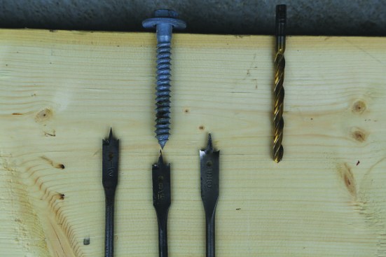
Clearance holes for 1/2-inch lag screws and bolts have a narrow range: 17/32 to 9/16 inch. A 1/2-inch drill bit is too small, and a 5/8-inch bit is too large.
A pilot (lead) hole through a rim joist should be about 5/16 inch for lags.
A lag screw also requires a clearance hole through the ledger (in the same size range as for a 1/2-inch-diameter bolt), plus a smaller pilot hole through the house rim joist and wall sheathing. The pilot hole should be the same diameter as the root of the screw portion of the lag, generally 5/16-inch diameter.
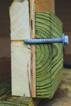
Bolts must penetrate through to the inside of the rim joist far enough to accommodate a washer and allow a nut to fully engage the threads. Lag screws must penetrate through the rim joist by the length of the tapered portion at the end, typically about 5/16 inch to 3/8 inch. Bolts and lags must be tightened enough to draw the ledger and rim joist firmly together, but not so tight that the washers compress the wood on either side.
Whether you use bolts or lag screws, there must be access to the inside of the rim joist in the house for the building inspector to evaluate the ledger attachment. Some builders believe that using lag screws allows them to avoid cutting into a finished ceiling, since no washers and nuts have to be installed. But when inspectors can’t verify the rim-joist material, view the edge distance of the fasteners on the inside of the rim joist, or check the penetration of the fasteners, they can’t conclude that the deck will be adequately supported by the ledger. In that case, the deck will have to be designed and built to be completely self-supporting.
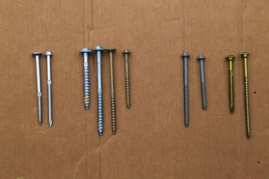
Proprietary structural screws don’t require predrilled holes and have a wider positioning range through the ledger, rim joist, and even the mudsill or wall plate. Pictured (from left to right): 1. Mitek WSW Pro Series washer head and hex head exterior screws; 2. Simpson Strong-Tie SDWH HDG (short and long) screws, coated SDWS, and coated SDWH Timber-Hex screws; 3. FastenMaster LedgerLok (long and short) screws; 4. GRK RSS (short and long) screws.
Structural Screws
Instead of 1/2-inch-diameter bolts or 1/2-inch-diameter lag screws, many deck builders now use proprietary structural screws for attaching deck ledgers. For those to be an acceptable alternative to lag screws and through bolts, manufacturers must have their screws tested and obtain third-party evaluation reports that can be presented to a building department. It is up to the local building official to accept or reject the use of these screws, so always check with the building department before using them.
These structural screws have a smaller (about 1/4 inch) diameter than code-specified bolts and lag screws, so they don’t require pilot or clearance holes, resulting in faster installation and less labor. They’re coated for exterior use and compatible with the latest types of pressure-treated lumber, and have head styles with integral washers (hex and flat/flush). They typically offer a wider installation range on ledgers and rim boards, with live load capacities that are greater than 40 psf. Most can be used with a variety of engineered rim boards.
When using structural screws, follow the manufacturer’s instructions and building code reports, rather than the tables in the IRC. Most manufacturers provide deck-ledger spacing tables that follow the IRC fastener-table format, with joist spans in columns and different rim-joist materials and live loads in rows. However, the proprietary screw spacing will generally be closer for a given span than the code table for 1/2-inch-diameter bolts or lag screws, so you do need to refer to the manufacturer’s information. Each table is unique to each manufacturers’ screws, so you can’t substitute the instructions of one company for the screws of another.
While the spacing may be different, some of the same installation provisions for the code-specified fasteners apply to structural screws. For example, you can’t countersink screws, and you can relocate a screw that interferes with a joist or hanger position by up to 3 inches to the left or to the right. You’ll still need to provide access to the inside of the rim joist for the code inspector to verify that the screws are adequately engaged (refer to the instructions for how far the screw tips must penetrate the rim). One benefit to using structural screws is that some manufacturers permit the screws to be installed into the mudsill or top plate of a wall, not just into the rim joist. That widens the range of heights you can position a ledger at so the deck can be set a full step down from the inside of the house, if desired.
Chuck Lockhart
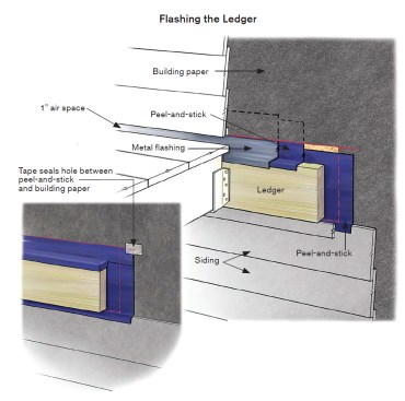
The IRC requires ledger flashing (per R703.4) but doesn’t provide any details. Here is the general approach followed by the author.
Next Steps
Ledger installation takes planning and precise execution to ensure a safe deck, and it shouldn’t be rushed. When installed properly, a deck ledger will handle the design loads for many years to come. The next step is to protect the ledger and the wall that it is connected to from water damage. I’ll cover that in detail in the next installment of this three-part series.
Photos by Mike Guertin