Note: This article was first published in 1991 before the use of engineered lumber was common. This article does not cover all the details specific to engineered wood systems, but many of the principles remain the same and many of the same mistakes are still being made.
Over the past 17 years, first as a builder and then as a representative of the Western Wood Products Association, I have traveled extensively, talking to builders and code officials to see how framing is done throughout the country. While I’ve found regional differences, I’ve also found a few serious framing problems that tend to crop up everywhere, again and again.
All of these problems are covered by the model building codes. A given problem might occur because the builder doesn’t know better, or because framers are paying more attention to other construction needs. Either way, these framing defects not only cause trouble with code officials, but cause problems big and small down the line.
Here are some of the most common framing errors I come across, along with code-approved, structurally sound solutions.
Framing Openings Cut in Floors
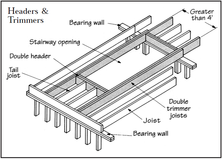
A common problem occurs with floors when subs cut through joists to make room for plumbing runs, hvac ductwork, or other mechanical elements. The loads these cut joists supported must be properly transferred to other joists. You can do this using header joists, endnailed across the cut ends of the interrupted joists, to carry loads to the adjacent trimmer joists. Where the header has to span a space less than 4 feet wide, a single header end-nailed to the trimmer joists will do.
Things get more complicated if the header must span more than 4 feet. If that’s the case, both header and trimmer joists should be doubled. The doubled trimmer joists must be nailed together properly (with spaced pairs of 16-penny nails every 16 inches) so that they act as beams. The header joists must be appropriately anchored to the trimmers. End nails will do for header spans up to 6 feet; beyond that, use hangers. Any tail joists over 12 feet should also be hangered.
When you’re framing the floor, check the blueprints to see where any such openings might go, and header off any joists that might be in the way in advance. It’s much easier than trying to work from underneath the subfloor later.
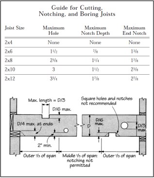
In dimensional lumber joists, never cut holes closer than 2 inches to joist edges, nor make them larger than 1/3 the depth of the joist. Also, don’t make notches in the middle third of a span where the bending forces are greatest. They should also not be deeper than 1/6 the depth of the joist, or 1/4 the depth if the notch is at the end of the joist. Limit the length of notches to 1/3 of the joist’s depth. Use actual, not nominal, dimensions.Note: Since this article was first published, engineered wood I-joists have largely taken over as the predominate floor framing material. The notching requirements vary greatly for wood I-joists. Consult the manufacture literature for the specific engineered wood system you are using, as the requirements vary even by manufacturer.
Holes and Notches
Whenever you cut a hole or notch in a joist, that joist is weakened. You (and your subs) should avoid this whenever possible. And when you absolutely have to cut or notch, you should know the rules for doing it in the least destructive manner.
The above table shows proper guidelines for cutting holes and notches. Straying from these guidelines weakens the joists and risks a red tag from the building official. Trying to fix such problems can be very costly, since it usually involves redoing the plumbing and electrical work along with replacing or doubling the joists.
Ripping long notches in floor joists, such as to make room for grouted entry floors, weakens the joists unacceptably and violates all codes. Instead, you need to use smaller dimension milled lumber of a higher grade or set closer together. If necessary, you can fur at the ends to bring non-grouted areas up to level.
When Notch Becomes Rip
Occasionally, what might be thought of as a notch turns into a rip, such as when floor joists at the entry of a home are ripped down to allow underlayment for a tile floor. Unfortunately, ripping wide dimension lumber lowers the grade of the material, and is unacceptable under all building codes. You should frame these areas with narrow joists of a higher grade or stronger species, making sure they can carry the load.
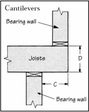
When a cantilever supports a bearing wall, the distance it extends beyond its support (C) should not exceed the depth of the joist (D).
Bearing Walls on Cantilevers
How far can a conventionally framed cantilever extend and still support a bearing wall?
Most of the confusion about how far a cantilever can extend beyond its support stems from an old rule of thumb used by builders and code officials alike: the rule of “one-tothree.” This states that a joist should extend back inside the building at least three times the length of the cantilevered section — if the cantilevered section hangs 2 feet out, the joists should extend at least 6 feet in.
This rule works fine for nonbearing situations. But it does not apply to a cantilever that supports a bearing wall. In this situation, the maximum distance that joists can be cantilevered without engineering them is a distance equal to the depth of the joists. So if you are using 2×10 floor joists, the maximum cantilever for those joists supporting a bearing wall is 91/4 inches. Beyond this distance, shear becomes a serious factor, as does the bending moment at the support. This combination could eventually cause splitting of the cantilevered joists. The only way to work around this problem is to have it engineered.
Broken Load Paths
A similar alignment problem relates to maintaining vertical load paths. All loads start at the roof and transfer vertically through the building to the foundation. If they aren’t transferred properly, you can end up with cracking of interior finishes or sagging framing. Many cracking problems written off to “settling” are actually due to what might be called broken load paths — paths that end up putting loads on areas not meant to carry them. This is one of the most common framing errors I see, and one to which many building inspectors pay close attention.
Misplaced struts. One example I see over and over again is a raftersupporting strut carried down to a nonbearing partition below. Occasionally I even see these struts resting on “strong backs” — 2x bracing run across the top of the ceiling joists to help brace them. This is a sure way to create cracking in the walls and ceilings below.
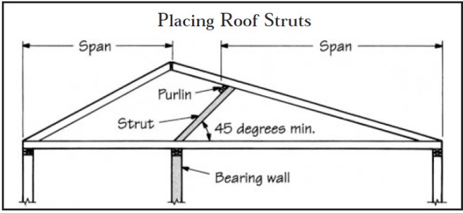
Struts supporting rafters should always land on bearing partitions. Also, the strut should not drop below a 45-degree angle.
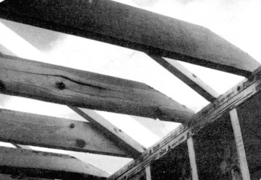
Of course, rafters do need to be supported when their lengths exceed their recommended clear spans. But the struts should carry down to bearing partitions, as shown.
The struts should be braced to a purlin running across the rafters above them, and they should form an angle of 45 degrees or greater to the horizontal. Finally, the struts must support the rafter so that it has no unsupported length longer than its recommended span. If you can’t do that and still reach a bearing partition without dropping the strut below 45 degrees, you need to upsize the rafters.
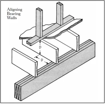
If a bearing wall doesn’t line up with the support below, it should lie no farther away than the depth of the joists (D). If the joists are engineered lumber, the walls and support must align exactly.
Misaligned bearing walls. In other instances, loads carried by bearing walls or posts must be transferred through floor systems. If the bearing wall or post above doesn’t line up closely enough with a bearing wall, post, or beam below, the floor joists in between can be overstressed, causing severe deflection. This can eventually split the joists, as well as cause finish cracking problems.
How closely must they align? Bearing walls supported by floor joists must be within the depth of the joist from their bearing support below (just as with cantilevers).
This code requirement applies only to solid sawn wood joists. Engineered products such as wood Ibeams are required to have the loads line up directly over each other, and special blocking is required. Special engineering of either dimensional or engineered lumber may allow placing loads at other locations, but you shouldn’t try it without consulting an engineer first.
Bringing columns to foundation properly. If you use a column to support a beam or other member, make sure it bears on something that can in turn support it. A common mistake is to rest one on the floor, without extra blocking or support beneath. Doing this can crush the underlying joists.
Columns shouldn’t rest on unsupported floor joists; they should run continuously to the foundation, or (if you must have a clear space beneath) to an engineered beam or header to transfer the load out to other columns or bearing members. Columns shouldn’t rest on rim joists either, for similar reasons. If you need to rest a column at the rim, add full-depth vertical blocking inside the rim joist the full depth and width of the column base, so that the load is transferred through the blocking to the foundation.
Puny Hangers
A simple but common framing error is hanging a three-member beam (such as three 2x10s nailed together) from a double joist hanger. This usually occurs because triple hangers are hard to find. But if only two of the three members are supported, then only two carry the load. The third member just goes along for the ride. Toe nails or end nails are not going to make it carry the load.
If you’re going to use a hanger, use one that holds everything, and use the right size and the correct nails. Undersized hangers and inappropriate nails will weaken the system.
The correct hanger is necessary to carry the vertical load as well as to laterally support the member to prevent rotation. And without the correct nails, the hanger doesn’t mean much. Eight-penny galvanized nails or roofing nails won’t do. You can buy regular joist hanger nails that are heavy enough to handle the shear stress, yet only 11/2 inches long so that they won’t go clear through the lumber and possibly cause a split.
Of course, the best way to support a beam is from beneath. When possible, use a beam pocket or a column directly under the end of the beam. Be sure the full bearing surface of the beam is supported clear to the foundation.
Overtapering joists to fit beneath roofs creates inadequate joist depth at the plate.
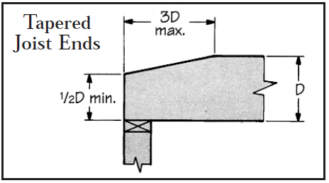
A proper cut leaves at least half the depth of the joist.
Tapering Beams and Joists
It’s sometimes necessary (or at least convenient) to taper the ends of ceiling joists or beams to keep them under the plane of the roof. But by reducing the depth of the joist or beam, you reduce its load-carrying capacity.
If you must taper-cut the ends of ceiling joists, make sure the length of the taper cut does not exceed three times the depth of the member, and that the end of the joist or beam is at least one-half the member’s original depth.
With taper-cut beams, you should also check the shear rating. If you can’t meet this criteria, you’ll probably have to lower the beam into a pocket so that enough cross-section can be left, after taper-cutting, to carry the applied load.
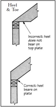
Setting a rafter’s toe on the top plate risks splitting the rafter and causing the roof to sag. The inside edge of the level cut, or heel, should rest on the plate.
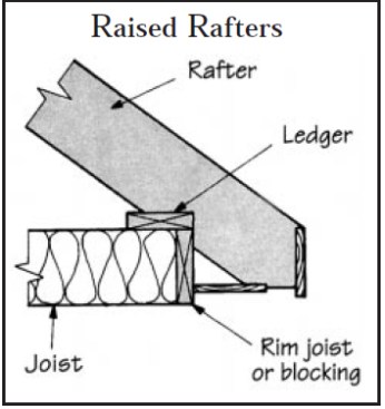
When nailing rafters to a ledger over joists to make room for insulation, use a rim joist to keep the joists from rotating.
Rafter Cuts
Another area that inspires excessive cutting is the level cut of the seat of a rafter. Many times, especially on low slope rafters, this level cut becomes a long taper cut on the tension (lower) side of the rafter. If the bearing point on the rafter is at the heel (interior side) of the cut, there is no problem. But usually these long cuts put the bearing point near the toe. This reduces the effective size of the rafter, producing stresses that can create splits at the bearing point, and eventually a sagging rafter.
To prevent this, cut your rafters so that the heel rests on the plate. This will mean using a slightly longer rafter. It will also give you a few extra inches between the top of the exterior wall and the roof sheathing. This translates into more room for attic insulation to extend over your outside wall, reducing those cold spots that can cause condensation or ice-dam problems at the eaves.
Raising the Rafters
Another way to add room for attic insulation at the eaves is to set the rafters atop a ledger board running perpendicular over the ceiling joists. Unfortunately, builders who do this often fail to put in a rim joist or block the ends of the joists to prevent them from rolling over. The resulting design creates, in essence, hinges at the top and bottom edge of each joist. With a strong enough lateral force, such as a high wind or a strong tremor, all the joists could rotate and fall over — bringing ledger, rafters, and roof crashing down onto the now-flat joists.
To prevent this, install full depth blocking between all joist ends or a rim joist nailed against the ends of the joists. Either solution will also provide a baffle to prevent air from penetrating the ends of the batts and keep the batts (or blown-in insulation) from creeping into the eaves.
Blocking is also a good idea where joists lap over a center girder at foundation level or over a support wall at second-story level. If the centers are unblocked, the job of keeping the joists upright falls to the nails holding the floor sheathing to the joists.
These nails just aren’t designed to resist the strong sideways forces created by wind or earthquake. Fulldepth 2x blocking over center supports will prevent the joists from rotating in such an event. The blocking also stiffens the floor, since it stops the rotation caused by deflection of the joists under load.
What if a few of these blocks get knocked out by mechanical contractors putting in ductwork or plumbing? That’s not usually a problem, as long you don’t remove consecutive blocks, so that each joist is blocked on at least one side.
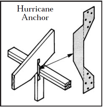
Nailing rafters to plates, and plates to studs, is not always enough to resist high winds. Hurricane anchors at 4-foot intervals will securely tie rafters to studs.
Connecting Rafter to Wall
Conventional construction leaves too little connection between rafters and walls. Nails connect rafter to plate and plate to stud, but do nothing to connect the rafters to the wall itself. Such structures are subject to damage from the high, near-hurricane force winds that sooner or later blow across virtually every roof.
As a result, the building codes are beginning to get more restrictive about how rafters and trusses are tied to the rest of the building. For example, the 1991 Uniform Building Code has added Appendix Chapter 25, which applies to high wind areas. Under its requirements, rafters or trusses must be tied not just to the top plate, but to the studs below at 4- foot intervals. This means using some kind of metal connector to provide a positive tie to the studs.
The answer is the hurricane anchor (see Figure 10). You don’t need to face a hurricane to need it — winds of roof-damaging gale force blow in most parts of the country. If you build in an area subject to high winds (or seismic conditions), you should consider using these or other holddowns


