Download PDF version (894.5k) Log In or Register to view the full article as a PDF document.

by Fred Ambrose

Image
Image

Our company specializes in oceanfront construction and rehab in southeastern Massachusetts. We do our own foundation work because of the control it gives us over the schedule. In some parts of this area, digging down is likely to uncover a mushy mix of sand, peat, and clay, not to mention a high water table. Since these soil conditions won’t support a conventional concrete foundation, local homes have traditionally been built on wood pilings, which allow floodwaters to wash in and out freely without undermining the structure.

The job shown here involved replacing a rotted piling foundation. The house stands along Provincetown’s historic harbor, where it’s common for 19th century buildings to be separated by only a few feet. This crowding leaves little or no space for conventional excavation; besides, trenching in the loose sandy soil risks undermining neighboring houses.

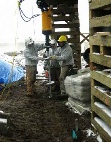
So for this job we decided to use helical piers, which looked to be an ideal solution because they require no excavation and can be driven quickly even in tight quarters (see “Helical Pier Foundations for Problem Sites,” 5/04). We obtained certification in the Chance Helical Pier Foundation System (573/682-8414, www.abchance.com) and purchased the equipment needed for installation, which included a hydraulic auger adapted to our excavator’s boom and a computerized torque meter. Altogether, it cost around $8,000.

Engineered Design

To design the foundation, we called on structural engineer John Bologna of Coastal Engineering Co., a firm familiar with the local geology and structural requirements. His knowledge of surrounding properties led John to expect alternating layers of sand, peat, and clay, with water at 4 feet below grade.

Based on this information, he specified a reinforced concrete grade-beam footing supported on helical piers spaced about 9 feet apart and driven to a minimum depth of 22 feet (see Figure 1). On top of the grade beam, a 10-inch-thick stem wall would support the new floor framing. Flood vents in the stem wall would allow high water to wash in and out, preventing the wall from collapsing in a surge.

Image

Figure 1. Grouting adds surface area and lateral friction to the column, increasing its capacity. It also adds a layer of protection against corrosive soils.

House Overhead

A major consideration was how to install the pier-and-beam system beneath a structure that couldn’t be accessed from all sides or raised and moved aside. The neighborhood’s historic classification barred complete demolition and replacement of the house, certainly the easiest approach.

Instead, we raised the house 4 feet, lifting it by the first-floor ceiling joists. We then cut away the ground-floor framing and installed steel I-beams and cribbing to support the second story. This gave us 14 feet of clearance, just enough to maneuver the excavator boom and its hydraulic auger attachment over the pier locations.

Giant Screws

Pier design varies according to soil conditions and loading requirements. Each steel pier consists of a lead section with one to four helical bearing plates that thread into the soil with minimal disruption, like a giant wood screw. The lead section pulls plain square shaft sections — which are bolted on in sequence — behind it. The last embedded shaft is cut to the desired height above grade and capped by a flat 8-inch-by-8-inch steel bearing plate, which is welded in place. The plate transfers the structural load to the pier.

For this job, we used “8-10-12” triple-helix lead sections (the numbers refer to the successive diameters of the three bearing plates) and a 1 3/4-inch-square shaft. Shaft sizes range from 1 1/4 to 2 1/4 inches square.

Concrete grout is used in certain helical-pier installations to increase lateral friction and thereby gain additional bearing capacity from an otherwise slender steel column. Grouting also helps protect the hot-dipped galvanized steel from corrosive soil; on this project, where salt posed a concern, grout was specified.

Giant Screwdriver

The auger attached to the arm of our track excavator is basically a giant hydraulic screwdriver, capable of producing 12.5 kips (12,500 pounds-force). We first turn the lead section into the ground to its full 5-foot depth, then attach a proprietary displacement plate to the shaft (Figure 2). When rotated, the displacement plate thrusts the soil aside to create a grouting cavity around the shaft.

Image
Image

Image
Image

Figure 2. Helical piers don’t remove material the way an auger does; instead they screw into the soil with minimal disturbance. A displacement plate, shown here upside down (top left) and added to the top of the lead section (top right), creates a void around the shaft as it is screwed into the ground. A 6-inch-diameter PVC casing fits onto the displacement plate and is pressed into the soil along with the first plain shaft section (bottom left). Incremental marks on the casing allow the insertion torque to be tracked at 1-foot intervals. Grout is poured in as each additional section is coupled and driven (bottom right).

Friction-fitted to the digging plate is a 4-foot length of 6-inch-diameter PVC casing. The casing is pressed down along with the next shaft length until it’s just about flush with the grade, and becomes a reservoir for introducing grout as shaft sections are added. We use a 2-to-1 sand mix with Type II cement and just enough water to make the grout flow. The grout is pulled downward by gravity and the square shaft’s rotation, following the digging plate to eventually encase the entire length of the pier above the lead section.

Monitoring torque. There are a few accepted ways to determine when you have reached the pier’s designed capacity. The method we use is the most precise, relying on a computerized torque indicator that delivers a constant readout of the hydraulic pressure delivered to the auger as it turns the shaft. We mark each shaft section at 1-foot intervals and record the readout as each mark reaches grade level (Figure 3).

Image

Image

Figure 3. A torque indicator with a direct feed from the auger head measures the hydraulic force required to turn the pier. A worker logs each pier’s insertion, noting the torque reading per foot of insertion. Readings generally increase with depth; sudden drops indicate voids in the strata, such as a peat layer. Torque is measured in foot-pounds and converts to bearing capacity at a ratio of 1-to-10. Thus, a reading of 4,200 foot-pounds indicates the pier has a 42,000-pound capacity. Pier installation is complete when design depth and capacity are reached.

While the engineer’s design documents required us to submit for approval a complete record for each pier, an engineer was also on site during the first few installations to verify the field conditions and results.

Grade Beam

The reinforced-concrete grade beam — which looks just like a footing — is essentially a structural header spanning from one pier to another, providing full support to the building. We shoveled a shallow trench for the 30-inch-by-16-inch beam, then placed the prescribed rebar (Figure 4). There’s no need to dig in below the frost line since the beam rides on the piers, not on grade.

Image

Image

Figure 4. Bearing plates (above) are welded to the top of each shaft, just above grade. Vertical rebar dowels, welded to the bearing plates, provide continuity from the pier through the grade beam and stem-wall foundation.

On top of each pier’s bearing plate, we welded four #4 upright “dowels” with 10-inch horizontal legs to tie in the stem wall. This ensured full continuity from the bottom of the pier to the top of the foundation. We set similar dowels on 16-inch centers along the entire length of the beam for tying in horizontal rebar.

With the rebar tied and the beam formed, we pumped a 4,000-psi, 3/4-inch aggregate mix in from the street — about 90 feet away — using the excavator arm to direct the pump hose (Figure 5). We keyed the top of the beam to receive the 3-foot-4-inch-high stem wall, which we formed the following day. We set pressure-treated wood bucks inside the forms for the stainless steel Smart Vents (877/441-8368, www.smartvent.com), which will allow floodwater movement but exclude critters.

Image
Image
Image

Figure 5. The excavator operator guides concrete placement for the stem wall (top), which is tied to the grade beam with a hefty schedule of vertical rebar (above). Note the knockouts for the required storm vents (right).

It took us two-and-a-half days to install a total of 21 piers, at an approximate cost of $1,500 per pier. It took another week to tie the rebar, and form and pour the beam and walls. With the first-floor framing replaced and the entire structure unified with wind-resistant metal connectors, this house should stand for a long time to come.

Fred Ambrose is president of Ambrose Homes in Chatham, Mass.