I think before we talk about the pro’s and con’s of a monopour (pouring the footing and the stemwall at the same), it is important to define what makes a successful concrete day. We can start with the industry standards. For instance, the American Concrete Institute’s tolerances (ACI 117M-10) specify that foundations be no more than 11/16 inch out of level over 6 feet, and the NAHB says that walls should be no more than 1 inch out of plumb.
Most custom builders, including myself, would never be happy with those tolerances. My preference for the top of the wall is that it’s no more than +/-1/8 inch out of level over 6 feet and no more than 1/8 inch out of plumb. I also want the foundation to be relatively square: +/- less than ¼ inch over 20 feet (while ACI accepts ½ inch). In addition, my definition of a successful day includes “No extra concrete was ordered and all concrete was placed on the day intended.”
I should also note that while this was not the first time I used a monopour system, it was the first time I used one with an ICF foundation. The first time you do anything new it’s rarely perfect, and often there are lessons learned. So when trying new materials or techniques, I prefer to do so on a smaller project. Smaller projects typically mean less risk and/or re-work if things don’t go well.
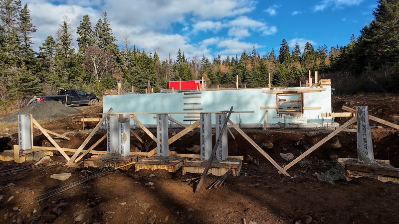
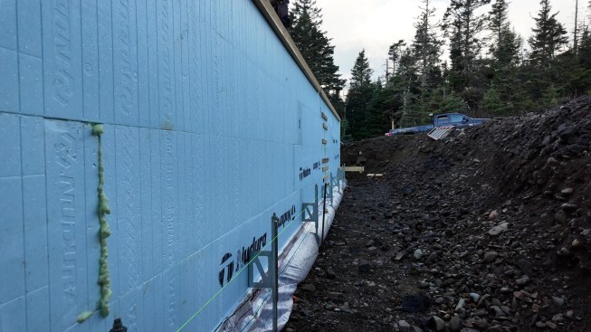
This home, which I’m calling the “Eventide Project” on Grand Manan Island in New Brunswick, Canada, was a good one on which to try out the system. Although it was a two-bedroom home, rather than pouring a full foundation for the whole house we only poured one under the service and mechanical areas, an idea I borrowed from Boston-area architect and JLC contributor Steve Baczek. What we ended up with looked like an oversized service corridor: 34 feet 3 inches long by 13 feet 3 inches wide. The bedrooms were supported by piers.
This project may be the first one we did where going small was a hindrance, but we will cover that in Lessons Learned, below.
We used the MonopourHD system from Fab-Form Industries in Delta, British Columbia. Their system of bracing and footing can be used with any ICF product (we used Nudura here) as well as with traditional poured foundations, and includes the “Fastfoot” bag footing form and wall bracing hardware. I have used Fastfoot on multiple projects, as far back as 20 years ago. So, while not having experience with an ICF monopour, I was familiar with some of the products involved. And Fab-Form was a great resource throughout the process, from planning to concrete placement. There are helpful details on their website, and I was able to reach them by phone and talk to a person if I had any questions.
Now let’s dive into the step-by-step process of using this system. The photos offer a visual overview while the text will provide additional detail.
Getting Started
Ideally you begin with a level site—I recommend no more than a
+/- 1-inch deviation from level over the entirety of the footing area. (This will also come up in Lessons Learned.)
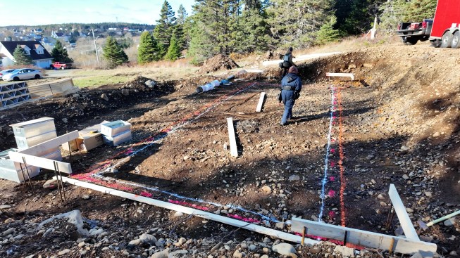
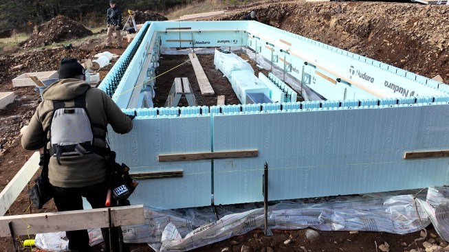
Begin by spray-painting your layout on the ground. I used rope as a guide to paint straight lines. Living in a fishing community, used rope is easy to come by and works very well for this application. String can work well too. It is also important to ensure your corners are located correctly and that the layout is square. I own a Stabila LA180 layout station with laser level but chose to calculate the diagonals of the corners manually, using the 3-4-5 method to confirm that all corners were square.
The directions from Fab-Form ask for three lines to be painted on the ground: one outside of the footing, one outside of the ICF wall, and one down the centerline of wall. I followed these directions, but I believe I could have gotten away with two lines: one down the center of the wall/footing, and one outside of the wall.
Batter boards were set up after the lines had been painted, but this could have been done before. While this may seem like we were going backwards, it was critical to the success of the project. You want your string lines about 4 inches above the top of your footing elevation. If your footing will be 10 inches thick, you want these strings at least 14 inches off the ground. The string also needs to be exactly 8 inches outside of the ICF wall, according to the directions, which is the minimum to get outside the MonopourHD brackets. (We followed that for three walls and used 10 inches for the fourth wall.) The strings should be easily taken down and put back up.
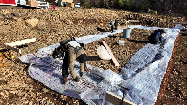
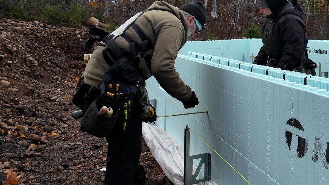
Aron Jones
The crew starts laying out lines for the footings and foundation…
Assembling The System
With the string in place, lay out the Fastfoot with its centerline directly on the top centerline you painted on the ground. You need a minimum 12-inch overlap at any joint between Fastfoot sections, and I recommend taping the joints at these overlaps to help prevent spillage (although I left one area untaped to give an escape route for any rainwater buildup). Then lay rebar on the centerline. The rebar is to keep the bag in place but then will be tied into the rest of the required system dependent on your local requirements and seismic zone.
Next, tie your footing rebar. The amount of rebar you use will vary by project region and zone, so be sure to follow the specifications in the plans. For this project we used three horizontal runs of 10M (1/2-inch) rebar in the footing. A splice length of 24 inches was required to finish. There was no specific tie pattern or spacing on the spreaders required by the plan. Ensure you keep the rebar within the footing layout.
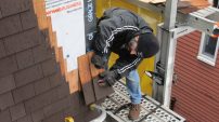
Start building your ICF wall. We use Nudura ICFs from Tremco on most of our projects, which is what we used here. I start in the corner and work inwards toward the stacking joints. A stacking joint, or marriage joint, occurs in the middle of an ICF wall when the dimensions of the ICF block cannot equal the wall dimensions in whole forms. Blocks are cut on either side of this joint to meet the required wall length. This process is repeated at the same point in each successive course, creating a vertical joint.
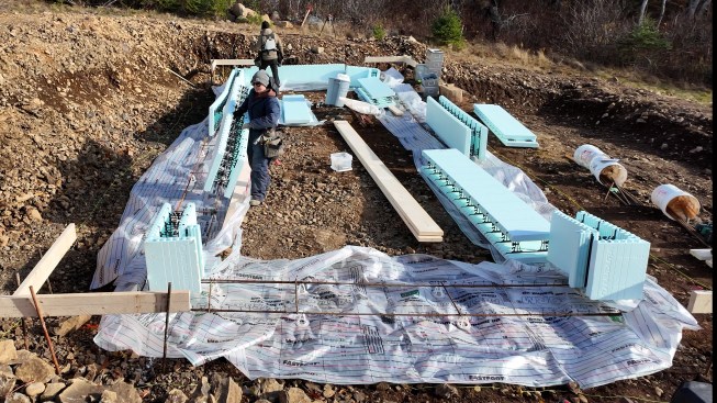
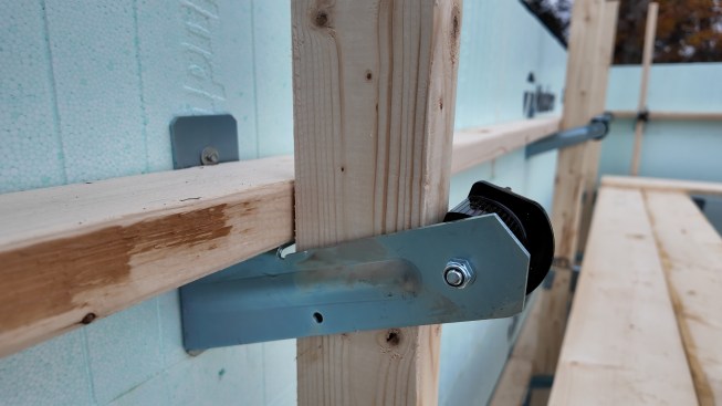
Aron Jones
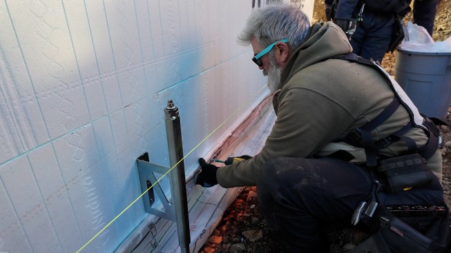
The HD bracket can be raised or lowered with a drill/driver or s…
With the first course complete, install rebar and form lock. This is a critical step. Form lock is a wire ladder that is snapped into the cavity of the ICF on the first course and then on every other subsequent course. It helps keep the walls straight and resistant to pressure. Once the first ICF course is complete, move on to the second one.
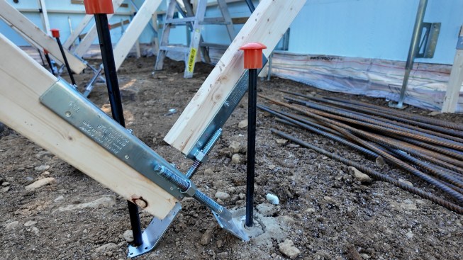
With two courses of ICF in place, install the MonopourHD brackets. These brackets hold and level your ICFs before and during the pour. Start at a corner, and ensure the bracket is at least 16 inches away from the inside corner. (This leaves room for the footing.) Install the brackets in pairs—one inside the form and one outside—at 6-foot intervals. Ensure you move the Fastfoot material, so it is not trapped under the bracket.
Using a laser level and a 2-foot spirit level, begin taking the wall to the required height. Think footing depth plus 36 inches (each course of Nudura ICF is 18 inches high). I found that getting the entire foundation close +/- ½ inch, then fine-tuning the elevation to perfect, was most effective.
Confirm the wall dimensions, check for square, and confirm you are on your layout. Tie the stacking joints together. Pin the MonopourHD brackets to the ground at corners and then work down the lines to ensure they stay on layout all the way along the layout lines. I used grade pins as they worked best for our soil conditions, but local conditions may vary.
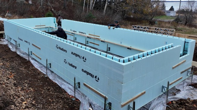
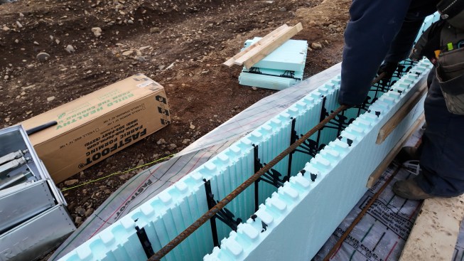
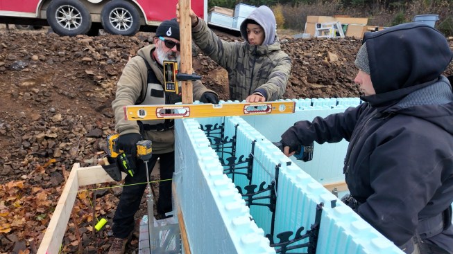
Aron Jones
With each block course and bracing attachment the crew confirm s…
Continue building the ICF wall as normal, complete with rebar and form lock as required.
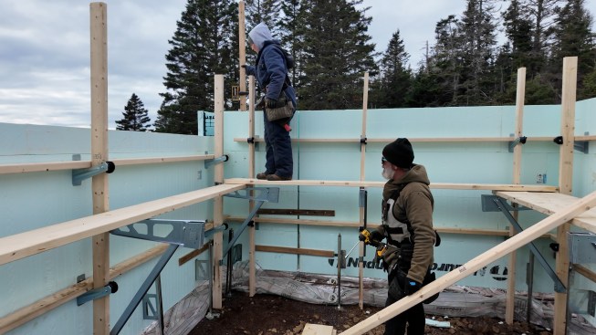
The wall is braced with Fab-Form’s “Zont” wall bracing system. This system is built around metal brackets called Zonts that are screwed into the web of the ICF wall. They’re connected to one another with 2-by horizontal walers and vertical strongbacks. The wall is braced, and plumb is adjusted with the company’s “Zuckle” wall aligner: a turnbuckle attached to a diagonal 2-by that can be adjusted with a drill. The system also includes “Zat” brackets that attach the vertical strongbacks and support a walkway for accessing the top of the forms.
Fab-Form has further information and videos showing how this all comes together on their website at fab-form.com.
Check the top of the wall for level. To adjust or fine-tune, unlock the cams (clockwise) on the “Zonts,” which ensures you aren’t lifting the bracing as well as the wall. These cams lock the 2×4 walers and strongbacks against the wall. Lock the cams (counterclockwise) when the adjustment is complete.
Place round rebar chairs on the footing rebar to space it up off ground. Place the vertical rebar and tie it to the footing bar if required. This is a great point for rebar inspection if required.
Attach the Fastfoot to the ICF. I used strapping for the attachment on our job, but Fab-Form recommends strips of plywood and I wish had followed that recommentation. (See Lessons Learned.) Use the “Fold Distance Calculator” on the Fab-Form website to determine your fold distance. The fold distance line is the line that’s flush with the top of the batten fastener. (Fold distance is also dependent on the size of footing you’re pouring.) Be sure to use the Monopour markings on the Fastfoot, not the printed lines for a conventional footing. Fab-Form recommends using a 1½-inch plywood batten in the fold to secure the Fastfoot to the ICF. I suggest you listen.
You are now ready for the concrete.
Concrete Day
Planning is key for any project, and probably more so for a monopour. Winter conditions, cold soil, and cold aggregate all affect cure times for concrete. Your project may require accelerator, depending on conditions and size.
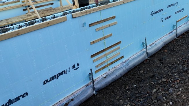
Aron Jones
The footings fill with concrete during the pour. One seam was left un-taped to allow water to escape.
This is our “Game Day.” There are no second chances with concrete. (Well, that’s not entirely true; but any second chances will be very expensive.) Tasks need to be assigned to individuals; everyone needs to know the plan. The crew needs to be adaptable to the situation and ready to help one another if things go sideways.
We began our concrete day by wheel-barrowing crushed rock to help get the concrete truck enough traction to get to the pump truck. We then added “Super-P” plasticizer to the concrete— a liquid plasticizer from Matrix Construction Products (matrixcp.com) that allows the concrete to flow more easily without adding water and accelerator to the truck.
The first lift of a monopour should fill the footing and about 6 inches of the ICF block depth. You want time for this lift to stiffen before going to your next lift. (It is important that you consider this carefully; ask me how I know).
While waiting for the footing to stiffen up we placed concrete in the columns on the project. As noted above, these columns supported the bedrooms. This was where lessons learned (as noted below) really started to kick in. We took a long pause (coffee break) while we waited for the concrete to stiffen up.
Aron Jones
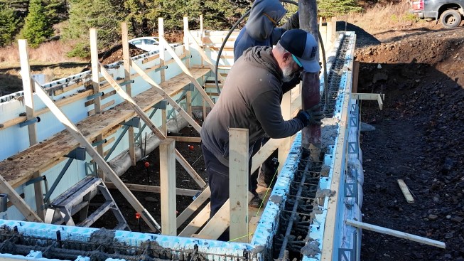
The author fills the ICF block while a helper vibrates the mix .
Then the pump truck driver indicated we had to start pumping again. We proceeded in conventional lifts, which for ICF is usually 4 feet, probably stressing this system to its max. Finally we got to the final pass to top up the taper blocks.
Lessons Learned
Here are the main lessons I learned on this project.
Ensure your site is level. We didn’t ask for a level crushed stone pad like we typically do, and we paid for it in labor needed to level out our first two courses of block. While the excavated area was close to level, close was not enough and resulted in extra work.
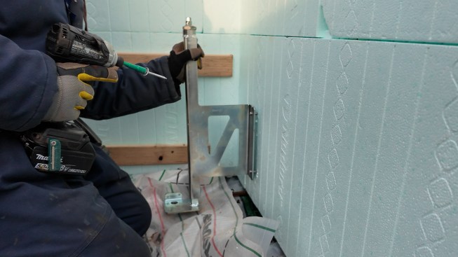
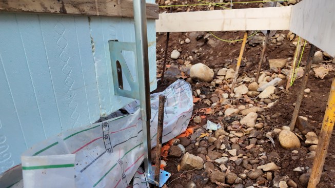
Aron Jones
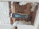
The strapping cracked, which nearly allowed a blowout of the footing during the pour. The author will be sure to use plywood strips as suggested in the future.
Wait until the wall is elevated by the brackets before placing rebar chairs on the footing rebar. Placing the chairs ahead of time created a hindrance when laying and joining block.
As I said, this was a situation where a small project turned out to be a hindrance. If you finish that initial lift of concrete too quickly (footing and 6 inches of block) there is no time for it to stiffen. Ordering your first truck with only enough concrete for the first lift (especially in colder months) will allow you to add the required amount of accelerator for the footing to stiffen in the required time frame.
Don’t use strapping! The instructions say to use 2 inch-wide strips of ½-inch plywood to attach the Fastfoot. (I think if I do a larger pour in the future I will use ¾-inch ply). I had standard 1-by strapping available and used that instead. I think if I hadn’t also used washer-headed screws the attachment would have fully failed. As it was, some quick thinking saved one area and the rest held up.
Would I Do It Again?
Yes, that is the answer. As carpenters, we’re used to adapting. We’ve watched tools evolve, materials change, and building codes tighten. A monopour is just another step in that evolution—one that rewards skill and planning. With the labor pool shrinking and build costs rising, monopour may be a technique you need to shave the costs of labor and resources. Is it perfect for every project and situation? No. But I do believe we will see more monopours in the future. In fact, my next new build may be a monopour.
Keep the conversation going—sign up to our newsletter for exclusive content and updates. Sign up for free