- Q. In many of the houses we work in, we are asked to evaluate the electrical system. We sometimes find 10/3 wire used on 110-volt circuits with 15- and 20-amp breakers in the panel. The installer has used the red and the black wire for separate circuits. Is this an acceptable installation or does it need to be pulled out and changed?
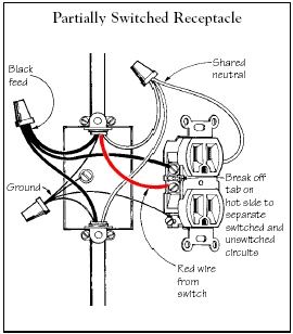
A. Rex Cauldwell responds: Whether or not this is an acceptable wiring scheme depends on where the wire leads.Partially switched receptacle. Three-conductor wire has two hots — black and red — and a white neutral. Though normally used for three-way switching, three-conductor wire is commonly used for duplex receptacle wiring as well. For a partially switched receptacle, for example, you would break off the tab on the brass side of the receptacle. The black and red wires are then connected to the now independent brass screws, one wire to each; it makes no difference which wire is on which screw. The neutral side of the receptacle is left intact. This makes the top of the duplex receptacle independent from the bottom, while they both share the same neutral (see illustration, below). The black or the red can go to a permanently hot feed, while the other goes to a wall switch, creating a switched outlet. This layout works well for switching on a table lamp in a room with no overhead lighting, but it doesn’t require heavy 10-gauge wire.
If you find a red wire and a black wire from the same three-wire cable coming into the panel, then going to separate single-pole breakers, you’ll need to check the installation. This scenario isn’t automatically wrong, but to be safe I would assume it was until I traced the wiring back from the panel. It could be one of several different things, but it’s usually a multiwire circuit or a 220-volt circuit.
Multiwire circuits. Three-conductor wire can be used to power a single circuit that would otherwise require two 2-wire circuits. For example, the black might feed a line of receptacles, while the red feeds a line of recessed light fixtures in the same area. The white is common to both (see illustration, below). If the loads on each wire are nearly balanced, the neutral wire carries only the unbalanced current, resulting in less of a voltage drop and wattage loss than the two 2-wire circuits would have. In this situation, the black and the red must be connected to the opposite phases in the panel to prevent overloading the neutral (white) wire.
This type of wiring is called a multiwire branch circuit. Though common in many areas, I do not recommend it. This system is governed by specific code regulations. A multiwire branch circuit must be able to disconnect both phases (that is, both branches) at one throw of the breaker. Therefore, these circuits must be ganged together. If someone does split the branches apart, and they both lead to the same phase on the panel, the neutral currents would be added together. Such an overload could have disastrous results. In addition, the receptacles, switches, and other devices on multiwire branch circuits must always be pigtailed, as shown in the illustration above. This is done to ensure that the neutral is not interrupted by a poor mechanical connection on the device (a wirenut is a much more reliable connection). Because of these requirements and the problems associated with multiwire circuits, my advice is not to use them for residential wiring where do-it-yourselfers are likely to muck around with them.
220-volt circuits. A similar scheme (red and black to opposite phases of the panel) is often used by do-it-yourselfers to power electric baseboard heaters or some other 220-volt circuit. But do-it-yourselfers often don’t know to use a double-pole breaker or don’t remember to connect the tabs between the breaker handles. This might also explain the 10-gauge wire: Someone incorrectly assumed the heaters needed the heavier wire. Do-it-yourselfers often don’t know that the breaker protects the wiring.
It would be impossible to list every conceivable situation, correct or incorrect, that you might have found. The bottom line is: Trace the wires. See where they’re going and what they’re connected to. Or throw the breakers and see what doesn’t work. Then trace it down.


