Hydronic radiant floor heating (HRF) is usually associated with concrete slabs. The reason is that slab-embedded systems are relatively simple to install: Long circuits of 1/2-inch to 3/4-inch polyethylene, polybutylene, or rubber tubing are arranged over a layer of welded wire mesh and then buried in concrete (see “Radiant Slab Techniques,” 8/92). But most homes have woodframed floors, and many of their owners are interested in radiant heat. Luckily, almost all HRF manufacturers have developed techniques for installing their equipment in these homes.
The tubing used in wood-framed floors is the same as that used for radiant slabs. Contractors’ costs for tubing in my area are 65¢ to 75¢ per linear foot (that’s 65¢ to 75¢ per square foot of floor area if the tubing loops are spaced 12 inches on-center). The installed cost of a complete HRF system — including tubing, underlayment, and underfloor insulation, but excluding the boiler — varies from $3 to $4 per square foot of floor area.
The Wet Approach
HRF systems for use with woodframed floors are classified as wet or dry, depending on whether or not they use a poured-in-place underlayment.
A wet system transfers heat to the living space through a thin slab that’s poured after the tubing is in place. The slab material consists of self-leveling gypsum or lightweight portland-cement-based concrete. The tubing is secured to the subfloor with snap-in-place plastic clamps or pneumatically-driven staples. The former are available from tubing manufacturers, while the latter are standard 1 1/2- to 2-inch-long staples. A special attachment connected to a pneumatic stapler adjusts the staple’s depth so its crown nestles against the tubing without crushing it. The underlayment is then poured to a thickness of 1 3/8 to 1 1/2 inches.
Wet systems have several advantages. During the pour, the mix fills the joint between the floor and the wall sole plate, reducing air infiltration along exterior walls. Once it’s dry, a wet system has excellent heat transfer because most of the tubing is in contact with the underlayment material. This means that you can run it with water temperatures of 105°F to 115°F — 15°F to 20°F cooler than the water temperature needed in a typical dry system. The slab’s thermal mass tends to even out temperature fluctuations caused by on/off cycling of the heat source. The slab also dampens sound transmission through the floor system, and can improve the fire resistance rating of the floor assembly.
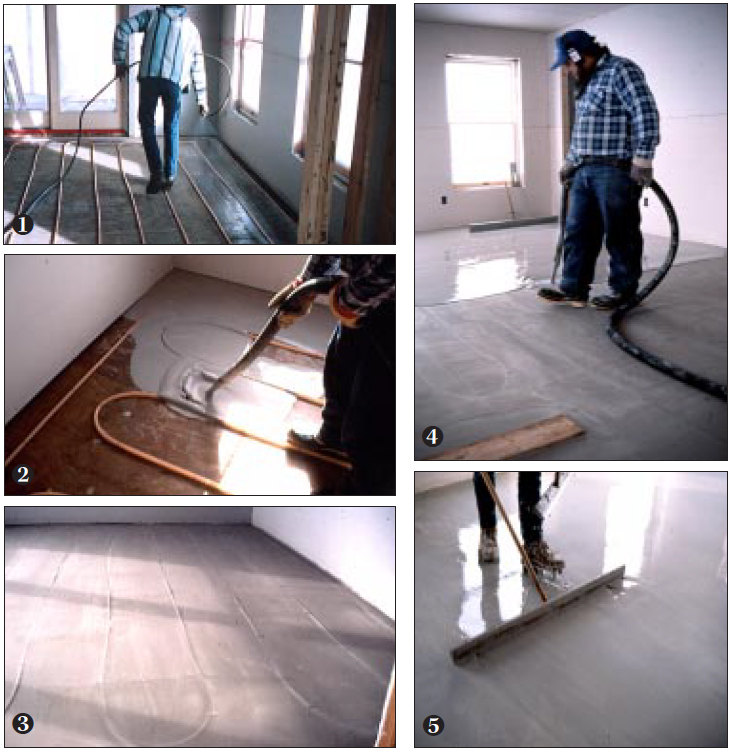
Gypsum-based underlayments are self-leveling but require large mixing and pumping machinery and must be applied by licensed applicators. The photo sequence (top of page) shows the installation of Gyp-Crete, the leading brand of gypsum underlayment. The tubing is fastened in place, then the floor deck is primed with a sealant that reduces water absorption into the plywood and improves the bond of the Gyp-Crete to the floor. To minimize shrinkage, the Gyp-Crete is poured in two “lifts” (a lift is the amount of material placed in a single pour). The first lift brings the level to the top of the tubing; the second lifts comes up to finished level and is floated smooth. The completed slab can be walked on within a few hours, but you’ll have to wait five to seven days — the time that the Gyp-Crete needs to fully cure — before installing finish flooring. Once cured, however, the slab will have a compressive strength of between 2,000 and 2,500 psi.
In my area, costs for a Gyp-Crete job range from $2 to $2.50 per square foot, depending on the size of the job and the distance the applicator has to travel.
Cement-based toppings. The main alternatives to gypsum-based underlayment are various lightweight, portland- cement-based toppings. Most redi-mix concrete plants will supply these topping mixes if you give them a specific “recipe,” which you can get from your tubing manufacturer. A typical formulation includes water-reducing agents, superplasticizers, and fibermesh to reduce shrinkage and control cracking (minor hairline cracks can still occur, but they have virtually no effect on heat transfer). This will provide you with a 3,000-psi slab for a total cost (labor and materials) of $1 to $1.30 per square foot. (A yard will cover about 200 square feet of floor area at a thickness of 11/2 inches and costs $80 to $120, depending on location and mix formulations.) The mix sets up quickly, so make sure your crew is big enough to place and level the contents of the truck in an hour or less.
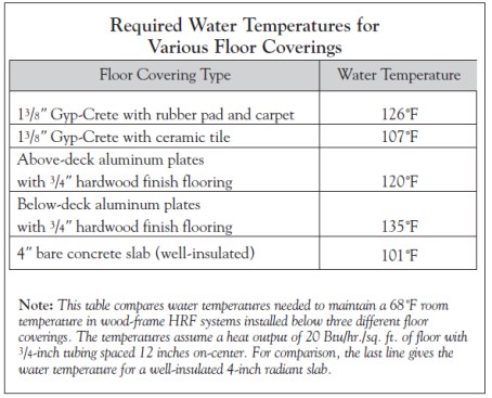
Finish flooring. Poured-in-place underlayments provide a good base for tile, carpet, or vinyl. Water temperatures in the tubing will vary, depending on the thermal resistance of the flooring material (see “Required Water Temperatures for Various Floor Coverings”). However, don’t install conventional hardwood strip flooring directly over a radiant floor. Instead, use a “floating” hardwood floor system (see “Radiant Heat & Wood Flooring”). Be aware that some strip flooring manufacturers will not warranty their product for use with radiant heat even when installed as a floating system.
Raise toilet flanges with plywood shims to accommodate the extra thickness of the slab.
Preparing for the Pour
Before choosing a poured-inplace underlayment, make sure that the floor structure can support the additional dead load of 12 to 14 pounds per square foot. Depending on the particular floor, this may require you to use deeper joists than you would normally use to keep deflection within acceptable limits (deflection limits vary depending on the mix; you’ll need to ask the underlayment manufacturer for the actual numbers). It’s best to do the calculations during the design stage, since you may have to decrease the joist spacing or use deeper joists. The extra load- ing may preclude the use of a wet system in some retrofits. When in doubt, have a structural engineer verify the floor’s ability to handle the additional weight.
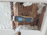
Finally, remember that the slab raises your subfloor height by about 11/2 inches. In order to compensate, you’ll need to adjust the heights of stair risers, door and window rough openings, countertops, door thresholds, and toilet flanges. You’ll also need temporary dams at stairwells and other floor openings to prevent spillage.
Dry Systems
Instead of using a slab to transfer heat from the tubes to the living space, a dry system relies on preformed aluminum plates. These systems fall into two categories, depending on whether they’re designed to be installed above or below the floor decking.
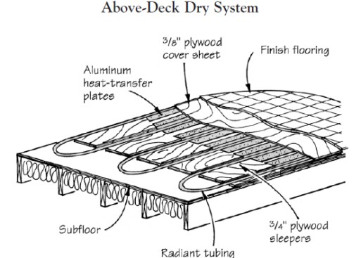
In a typical above-deck dry system, aluminum heat-transfer plates are supported on plywood sleepers. The plates and tubes are covered with a plywood cover sheet before the finished flooring is installed.
Above deck. The first type, the “above deck” installation, is shown in the illustration above. Aluminum plates that fit around the tubes are supported by 3/4-inch-thick plywood sleepers that fill the entire space between the tubes. A cover sheet of 3/8-inch plywood is then laid over the top of the fins. Although hardwood strip flooring may be nailed directly to the sleepers, I don’t recommend it. If your clients want wood, steer them toward a floating system.
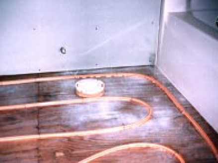
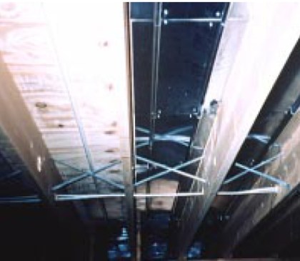
In a below-deck dry system, the aluminum plates wrap around the underside of the tubing. In new construction (top), the tubing and plates can be installed before the subfloor.
In a below-deck dry system, the aluminum plates wrap around the underside of the tubing. In new construction (top), the tubing and plates can be installed before the subfloor.
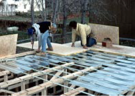
Below deck. The aluminum plates can also be installed beneath the floor deck, as in the images above. There are two ways to do this. In one, the tubes are laid on top of and perpendicular to the framing; then the space between the tubes is filled with wood sleepers. The sleepers support the single-tube aluminum plates and the whole assembly is covered with 3/4-inch-thick plywood subflooring.
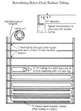
In the other below-deck installation, the tubes are routed between the joists, and double-tube plates are used to span the entire width of the joist bay. With this method every zone is supplied by a single length of tubing that must be pulled through holes in the joists and fed out into the joist bays one at a time (Figure 4).
In most dry systems, only about half the surface of the tube contacts the aluminum plates. This lessens the rate of heat transfer from the tube compared to wet systems. To compensate for this, higher water temperatures are required — 10°F to 20°F higher than for a thin-slab system. These higher temperatures don’t pose a problem for the tubing, but could preclude use of lowtemperature heat sources such as hydronic heat pumps.
Recommendations
Although no single HRF system is ideal for all installations, my usual preference in new construction is a wet system with a Gyp- Crete underlayment. This system is relatively simple to install and is easy to schedule with the other trades. As for performance, the slab’s thermal mass smoothes out temperature fluctuations, ensuring a fairly constant indoor temperature. I also like the stiffness the slab gives the floor and the way it dampens sound. And because wet systems use lower water temperatures than dry systems, a wet system can use a low-temperature heat source like a heat pump or solar collector.
If the job requires a dry system — which is usually the case when retrofitting floors with limited bearing capacity — the below-deck installation with the tubing running parallel to and between the joists is usually the least expensive. No sleepers or furring strips are needed, and you don’t need an extra layer of plywood for a cover sheet. The limitation of this approach is that you’ll need ready access to the underside of the floor deck, which must be free of pipes, ducts, and other obstructions.
Insulation. Whatever approach you choose, it’s important to insulate the underside of the floor. This is especially true over an unheated basement, or where you’re installing a finish flooring with a high thermal resistance, such as a thick carpet and pad. I specify a minimum of R-30 over unheated spaces like crawlspaces, R-19 over partially heated spaces like basements, and R-11 over heated spaces.
Design assistance. Nearly all HRF distributors offer some form of design assistance. Some will do the load calculations for you, or take your blueprints and plan the circuit layout without cost. Others sell software at a nominal cost so that the system designer can evaluate various tradeoffs (costs vary for different systems, but so does performance). Tubing manufacturers should also have lists of outside designers available in your area. If you’re new to HRF, then it’s worthwhile to shop around for a manufacturer who offers the level of technical support that you need.
Hybrid Hydronic Systems
One big advantage of hydronic heating is its versatility. Using a single boiler, you can install radiant heat beneath the floor tiles in a bathroom while running finnedtube baseboard everywhere else. The same boiler that’s used for space heating can also be used to heat domestic water, by routing the boiler’s output through a heat exchanger in an indirectly-fired hot water tank. The problem is that these loads require very different water temperatures. A radiant floor may use 105°F water, while the hot water tank needs to be kept at 160°F.
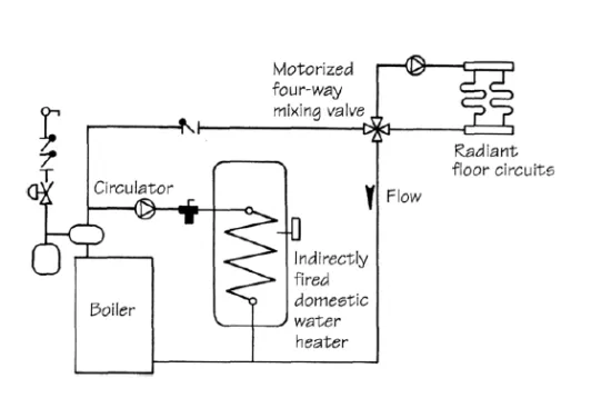
Figure A. The most common way to run a domestic water heater and an HRF system from a single boiler is to place each load on a parallel piping loop. A four-way mixing valve controls the temperature in the HRF system.
The most common solution is to place each load on a parallel piping loop (Figure A above). A parallel loop for domestic hot water originates near where the hot water supply exits the boiler, and ends close to the return. A motorized four-way mixing valve at the beginning of the HRF loop blends high-temperature water from the boiler with cooler return water from the radiant floor. This lets you adjust the water temperature in the tubing much as you would use hot and cold water valves to adjust the water temperature in the shower. Mixing valves can be expensive, however: A typical 1- inch-diameter four-way valve with its associated control system can cost from $600 to $950 for parts alone. For small jobs like single bathrooms, that can be greater than the cost of the radiant floor system itself.
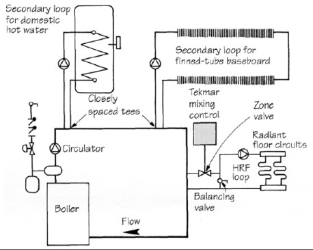
Figure B. An alternative is to place each load on its own secondary loop and use a 24-volt zone valve with an injection-mixing control unit to regulate the temperature. The valve mixes pulses of hot water from the primary loop with cooler return water from the HRF loop.
You can save money by using an alternative piping arrangement and a relatively inexpensive control unit (Figure B above). A continuous piping loop, called the primary loop, runs uninterrupted from boiler supply to boiler return, while each domestic hot water and hydronic heating load is connected to a separate secondary loop with its own circulator. The secondary loop’s supply and return tees are placed within a foot of each other on the primary loop. The temperature of the HRF loop is regulated by a standard 24-volt zone valve that’s placed between the primary and secondary loops. It’s operated by a Model 351 Injection Mixing Control that’s available from Tekmar Control Systems (see “Sources of Supply,” at end of article). Together, the valve and the control list for around $300 (the control lists for $233, while a typical 3/4-inch motorized zone valve costs about $75).
The Tekmar unit receives signals from three temperature sensors, one in the heated space, one on the warm water supply pipe to the HRF distribution system, and one outside the house. When the unit decides that the HRF system needs heat, it opens the zone valve to inject a pulse of hot water from the primary to the secondary loop. At a tee just beyond the zone valve, the hot water mixes with cool return water from the HRF system. The amount of mixing is regulated by a balancing valve that’s carefully set when the system is installed, then left alone.