Our design/build company performs a wide variety of building services. We’re equipped to handle every aspect of new construction and remodeling, including house-lifting and foundation and septic-system installation, as well as framing and finish carpentry, all in-house.
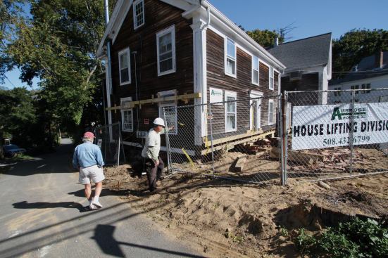
In September we undertook the restoration and remodel of a two-story early-1800s residence in the historic village center of Wellfleet, Mass. We began by lifting the house off its failing foundation and setting it back down on a full poured-concrete basement. This article will look at that process. As of this writing, we’ve moved on to a gut-remodel of the building.
Existing Conditions
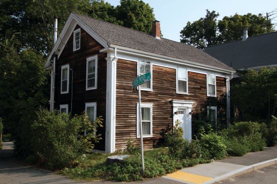
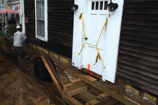
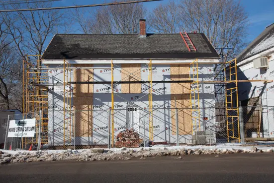
The house was built on a lot that sloped immediately down from street level, which set the front door sill about 9 inches lower than the sidewalk. Because no attempt had been made to adjust the grade to deflect runoff, water ponded against the foundation, eventually rotting the front sill beam. Also, the oldest part of the foundation consisted of a single thickness of mortared brick (common in the area’s sandy soils) set barely below grade without any footings. Consequently, the building had settled unevenly, stressing its timber frame to near failure. When we started work, the building department had already ordered the house vacated.
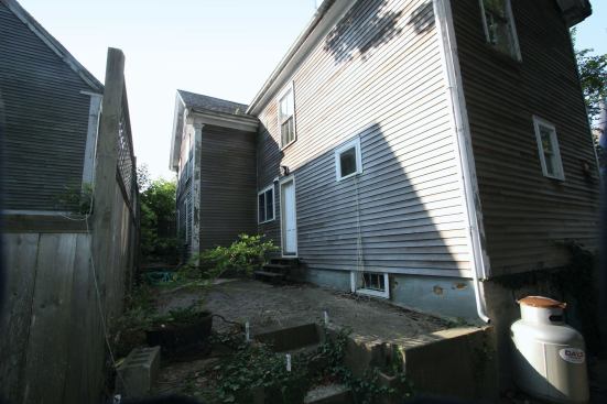
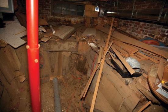
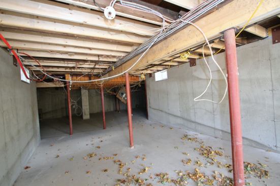
At the back of the original building was an extension that had been built in the 1920s on a full foundation of hand-mixed concrete interlaced with bricks and rubble. This part of the foundation was accessible through a door in the rear and allowed about 6 feet of headroom. Under the original structure, the builders had expanded the basement area by excavating to within a few feet of the older brick foundation, shoring it with small-diameter logs driven vertically, stockade-style. This innovative approach may have destabilized the grade, and a small forest of teleposts suggested a history of nerve-racking creaks and pops as the building settled.
Digging In
The shifting foundation had caused some of the tenons in the timber balloon frame to pull away—as much as 1 1/2 inches in places—from their mortises. Before we jacked anything up or worked on the sills, we stabilized these joints by running a heavy chain from a central interior timber through the tops of the first-floor gable-end windows to a pair of 6x6s running the full width of the building. We used a come-along to keep tension on the chain, which prevented the frame from spreading further during the foundation work. (Later, after the building had been set down on its new foundation, we would pull the joints tight and reinforce the connections.)
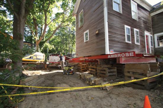
The rotted front sill had to be addressed before we did anything else. We stripped back about 2 feet of siding and sheathing across the front of the building. To create room to stack cribbing, we hand-dug pocket holes about 4 feet deep, undercutting the foundation near the corners and at the center. After stacking the cribbing, we used bottle jacks to raise the building just enough to slide in short lengths of 6x6s directly under the existing sill.
With the front wall supported by cribbing, we started removing badly rotted portions of the sill. Very quickly we confirmed our suspicion that the sill was almost completely rotted through along most of its length and that it would be best to replace it entirely before attempting to lift the building. We pulled a string-line from corner to corner as a reference for straightening the sagging timber-frame system, then jacked and shimmed until the bottoms of the four posts—one at each corner and two on either side of the central door—registered uniformly against the string.
With the front wall timbers in plane, we bolted a 6×6 ledger to the face of the frame along the entire length of the building, pre-drilling the four 8×8 posts to receive 1/2-by-12-inch lag screws. We used TimberLoks and LedgerLoks to secure the 2×4 infill studs, many of which did not run the whole length of the balloon frame and were supported by the sheathing. Then we set jacks on the cribbing and lifted the ledger to shift the weight of the structure off the sill, enabling us to remove it and fit a new, pressure-treated 6×6 member in its place. Including the stripping of the siding and sheathing, this process took a full two days.
Setting Steel
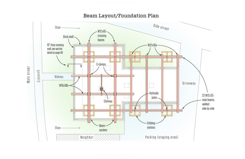
With the front sill replaced, we turned our attention to placing the steel I-beams needed for the lift. Since the building itself occupies most of this street-corner lot, access for inserting the beams was limited to the back, where we had a small staging area, and one side of the building at the front (see “Beam Layout/Foundation Plan,” below). Given the close quarters, we delivered mainly 16-foot lengths of steel, which we welded on site to create the lengths we needed.
Click to enlarge image below.
Tim Healey
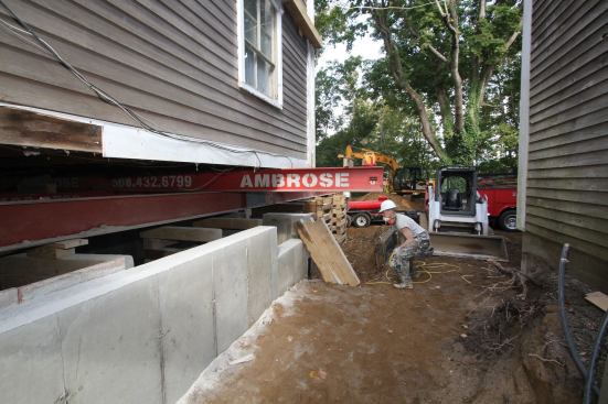
One of the design principles for lifting a beam is that its flange should be at least as wide as the web is high—nominally, a square section profile that prevents the beam from rolling over under load. This was a particularly important consideration for the two main beams, which would provide the direct jacking points for lifting. These two beams would need to be 50 feet long and would run outside the walls of the building’s narrower rear extension and under the original structure at front. We built them up from front to back using W12x35 I-beams welded side-by-side with their ends offset in a staggered pattern. Each 16-foot section weighed about 560 pounds, so we used our mini-excavator to wrestle them individually onto cribbing before welding.
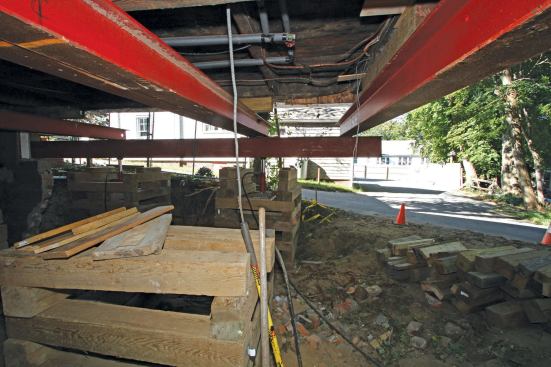
We wanted to set the beams as near to their final elevation as possible so we wouldn’t have to lift them very much later. Fortunately, the halfway point on these beams fell outside the foundation, so we were able to move them nearly into final position without having to reset the support straps that suspended them from the excavator. We set them level, at a height that left enough room for the shorter crossing members to fit between them and the underside of the floor framing. This sounds more straightforward than it actually was because we had to set up temporary cribbing stations at various locations under the front part of the building to support it while we excavated access points for the main beams through the old foundation. Ultimately, each of the two main beams rested on four cribbing stacks, two inside the foundation at the front and two outside the foundation along the rear addition.
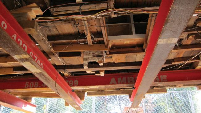
Next, we inserted the “needles,” or crossing beams, from which we would ultimately block up to support crucial locations under the building. In the addition, the joists ran across the width of the building and were mortised into a central carrying beam. We placed four needles parallel to the joists, shimming as needed to pick up the central timber and to make sure that all three sills in the addition were fully supported.
Dave Holbrook
The house was built on a lot that sloped immediately down from s…
In the front of the house, the joists ran the full width of the building, supported by two intermediate carrying beams that divided the floor system into three sections. To support this part of the house, we inserted two crossing beams, which would eventually rest on top of the two main 50-footers. Because of the tight conditions on the site and the need to work around a brick chimney in the center of the basement, moving these beams into position required a series of maneuvers. To place the first beam, which would run behind the chimney, we slid it in diagonally on top of the 50-foot main beam from the front left corner, then see-sawed it back and forth until it was perpendicular to the main beam and parallel to the front sill. The second beam went in a bit more easily, in front of the chimney.
We then hung two additional beams at a right angles to the crossing beams, aligned directly under the two floor timbers. To hang these beams, we used special heavy-duty Wilton C-clamps capable of supporting 15,000 pounds each. We snugged blocking between their flanges and the underside of the floor timbers to make a solid connection.
To pick up the chimney load, we punched a hole through the brick and flue tile and slid a scrap of tube steel through it. The standard alternating brick courses transferred the stresses and effectively held the chimney intact with no further reinforcement.
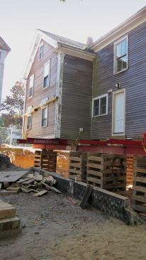
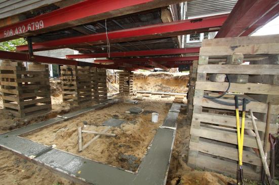
With all the needles placed, we brought in the nine-point hydraulic jacking system, which we had recently purchased used and had completely refurbished. A central manifold controls all nine jacks, which are driven by a single main piston. We set eight of these jacks under the main beams and lifted them just enough to transfer the building load off the foundation. Once we were sure that the entire structure was safely supported, we jacked it another 3 feet or so—high enough to get our skid steer underneath to complete the excavation. The maximum throw of the jacks is about 14 inches, so we had to reset them three or four times. Each reset involved blocking solid between the cribbing and the steel beams, resetting the jack, lifting, then blocking again.
Digging Down
Our goal was to set the building at a final elevation that would be 9 inches higher than it had been; this grazed the maximum ridge height allowed by the local zoning ordinance. At the same time, we wanted to provide enough headroom to allow us to set 8-foot form panels on top of new concrete footings. All these factors taken together meant that we needed to dig down about 12 inches.
At the rear addition, this posed no real challenge because the cribbing stacks stood outside the walls and out of our way. We dug down, deposited the fill in the staging area, and loaded it by excavator into our dump truck for removal from the site.
The front of the house was a different story because the cribbing was near where we needed to excavate for the footings. We dug as close to each stack as we could, set a new stack next to it, and transferred the beam load. Then we pulled out the original stack of cribbing and dug down to final grade. In all, we spent three days excavating—the sand and gravel soil made the digging easy, but resetting the cribbing took some time, as did pulling the fill out from under the house and loading it for removal.
Click to enlarge image below.
Foundation
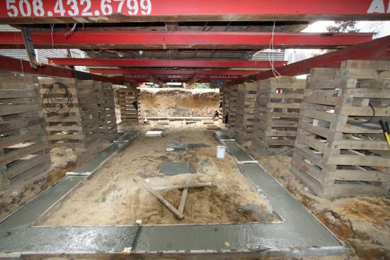
To locate the footings, we used a vertical laser to pinpoint the building corners, then offset the forms by 4 inches. We added 8-inch-thick pads for intermediate Lally columns and for the chimney. For all but the front wall, we poured standard 8-inch walls on 16- by 8-inch footings. With the grade falling steadily away front to back, this provided sufficient support for the structure.
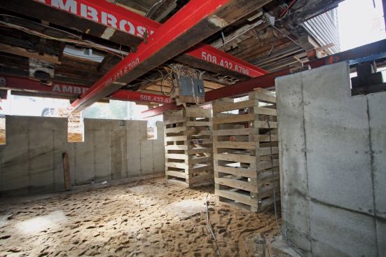
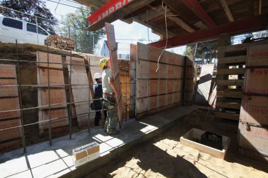
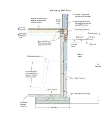
Because the front of the building was not far from the road bed, it called for a foundation that also functioned as a rugged retaining wall (see “Retaining Wall Detail,” above). Here, we formed a 4-foot-wide spread footing reinforced with #5 rebar set on chairs. After placing the concrete, we set #5 pins at 18-inch intervals to engage the 10-inch-thick wall. For reinforcement, we wired vertical and horizontal #5 bars in a uniform 18-inch grid and laid a final piece of rebar across the topmost form ties. We wanted to preserve the historical appearance of the foundation where it faced the street, so we formed in a ledge to support veneer brick across the front and part of one side. As was the case with all of the walls, we boxed pockets in the forms to allow room for the I-beams to project through when we lowered the building. These pockets were a little wider in the front section to make it easier to snake the steel crossing beams out from under the house.
In most places, we were able to chute the concrete directly into the footing forms, but we couldn’t use that method to pour the walls—the steel beams, the blocking, and the building itself presented too many obstacles. Instead, we hired a concrete pumping service and, for maximum maneuverability, specified a 2-inch delivery hose. This smaller diameter called for smaller 3/8-inch aggregate, so to ensure an optimal bond, we called for a high-strength 4,000 psi mix.
After stripping the forms, we gently lowered the building onto its new bearings. We pulled out the beams—including the welded-up 50-footers (which are already in use on another job)—one at a time, and then filled in the beam pockets with concrete block.
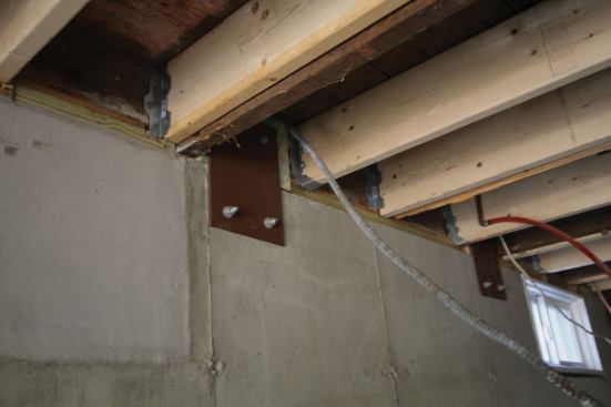
Before pulling the beam supporting the decommissioned chimney, we built a concrete-block pier to carry it. To tie the building to the foundation, we had a steel supplier cut and punch bolt holes in 1/4-inch steel plates, which we prime-painted and lagged to the foundation using a Simpson Strong-Tie epoxy anchoring system.
There was a considerable amount of re-framing needed to reinforce the old floor system, which we did mostly by sistering in new joists and piggy-backing some others. With a 4-inch concrete slab poured over a moisture barrier, the basement is complete, and we’ve turned our attention to helping the building face the next 200 years.
Fred Ambrose is president of Ambrose Homes, in Cape Cod. His son, Ezra, supervises field operations.