A companion article to French Landings: An Evolution in Building Elegant Stairs.
To layout a French Landing, follow this three-step process:
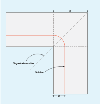
Initial sketch. I started with the plan for a conventional quarter-turn stair and penciled-in the location of a 3-foot-square landing (shown in drawing at left). On this stair, the guardrail will sit over the stringers at the ends of the treads, so I also penciled-in the walkline (shown in red) 12 inches from the guardrail—as it would exist for a conventional quarter-turn stair. I then drew a diagonal through the landing, extending it out past the inside corner of the landing. This diagonal will serve as a reference line for establishing my curved landing and treads.
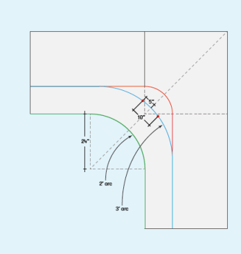
Defining the inside curve. I chose a 2-foot radius for the inside corner and drew an arc with the center point located on the diagonal. To represent the walkline on the French landing, I drew another arc with a 3-foot radius concentric to the arc with the 2-foot-radius. The intersection of this walkline with the diagonal reference line defines the midpoint of the curved walkline. Since I want the landing to equal the tread depth (10-inches), I measured 5 inches on each side of the diagonal. These two points define the curved edge of the landing (5 inches below the diagonal) and the edge of the first curved tread above the landing.
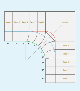
Stepping off the landing and treads. Using the two points that define the depth of the landing along the walkline, I can set my compass and step-off the scaled 10-inch treads along the walkline.
To establish the location of treads 4, 5, 6, and 7 (those that cross the walkline for the landing), I have to step-off the treads along the initial walkline I penciled-in for a conventional quarter-turn stair.
Defining the curves. The curved sections of the treads above and below the landing, as well as the landing itself, all have radii of different lengths. Each of the curved treads decrease in depth at the guardrail as they approach the 6-inch-deep landing (the minimum for an odd-shaped landing required to meet code).
My favorite way to figure out the variable tread curves is to use a technique adapted from William and Alexander Mowat’s “A Treatise on Stairbuilding and Handrailing,” originally published in 1900 (reprints from 1985 and 1997 are available from Linden Publishing):
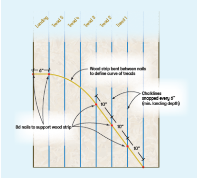
Take a sheet of plywood and snap out lines spaced 6 inches apart (the blue lines shown in the illustration at left). Starting in a lower corner, use a tape measure to find a diagonal between two chalklines that’s 10 inches long (the depth of a full tread). Mark three of these full-size-tread lines in a continuous line. Then take a thin strip of wood (ripped to about 1/8 inch, so it’s flexible) and clamp it on-edge to a few nails driven into the plywood where the three diagonal tread lines intersect your chalklines. Bend the strip of wood until it is perpendicular to the 6-inch chalklines. Each of the chalklines represents a tread, so I bend my strip across the number of chalklines that correspond to the number of treads I need before I get to my landing. Based on my plan drawing, I need to bend the strip in a curve that’s tight enough to cross treads 3, 4, and 5. The sixth will be the landing, and this is where ihe wood strip needs to be horizontal. I can then make tick marks at each of the chalklines on the strip of wood and use this as a story pole to measure the depths of the treads for treads 3, 4, and 5 (and these would be equal to treads 6, 7, and 8).
Using the lengths on my flexible wood strip (scaled to match my drawing) I can now step off these distances on the outermost curve of my layout drawing and connect these points to the ends of the straight sections of the treads. This will define the curves for each tread above and below the French landing. The beauty is that I can do this without needing any numbers except the depth of a full tread (10 inches) and the minimum depth of the landing (6 inches).
Return to main article.