I was hired to repair two timber columns in the basement of a 200-year-old building in Shirley, Mass., that had once been the post office and had served for a time as a hardware store. The building is currently zoned for mixed use; there’s now an insurance company and apartments. The building owner was concerned about two columns supporting the main girder in the basement that showed obvious signs of rot at the base. Both posts were buried in a concrete slab that had been poured over the dirt floor.
While the columns showed evidence of decay at the base, most of the timber above the floor line was sound. These columns were massive timbers from old-growth trees (the building was built in the early 1800s). To me, it didn’t make a lot of sense to replace the entire columns. Instead, I chose to join a short section of timber to the base of each column. The new column bases would bear on new, solid footings and be secured by steel connectors that would isolate the timbers from the concrete.
Temporary Support
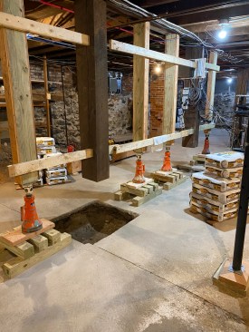
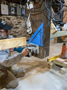
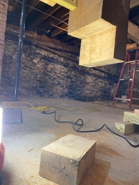
My first step was to lay down cribbing to spread the load and support house jacks and temporary posts. I stacked the cribbing on the basement slab, in-line with the main girder on each side of each post. For cribbing, I used pressure-treated, Southern pine 4x4s. I screwed five pieces together with a 2×6 on top and leveled them as one with composite shims to keep the jack flat and level. For the temporary supports on the jacks, I used 4×6 stock reinforced with ¾-inch plywood on each side to help stiffen these temporary posts. When supporting building loads, it is critical to keep the posts plumb, so I braced them with horizontal 2x4s that I secured to the upper portion of the columns I was repairing.
1
of 4
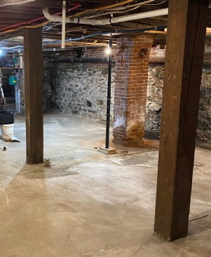
The basement before repairs shows the original timber support po…
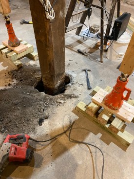
The basement before repairs shows the original timber support posts holding up the main beam.
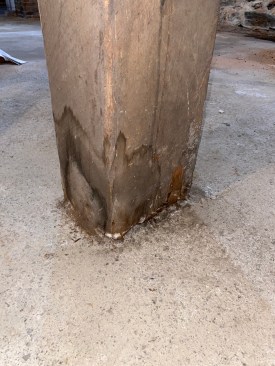
A closeup of one of the basement columns shows significant decay…
A closeup of one of the basement columns shows significant decay where the wood was encased in the thin concrete floor slab.
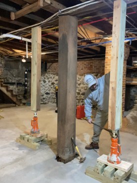
With house jacks supported on cribbing, the author began raising…
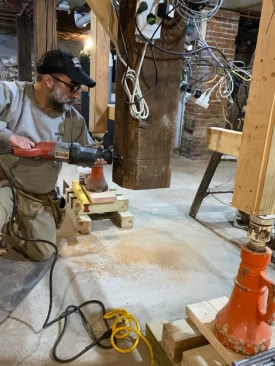
With house jacks supported on cribbing, the author began raising the jacks to take the weight off the old columns.
To free the posts, he cut through the slab and excavated around …
To free the posts, he cut through the slab and excavated around the posts prior to raising the jacks. Once the old column was loose, he stopped jacking.
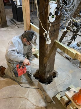
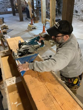
I wasn’t jacking up the building, just putting pressure on the beam above to take the weight off the old columns. To accomplish this, I chipped out the concrete around each post and dug down through the fill under the slab until I could feel the bottom of each column. Then I started raising each jack little by little, keeping my eye on a laser line trained on the bottom edge of the girder beam to make sure it wasn’t moving. Any movement of the beam and floor system might put pressure on the gas and water lines that ran through the floor above, and I certainly did not want to stress those old fittings. As I put pressure on the jacks, I kept pushing the old columns until I could feel them move slightly, which meant they were no longer carrying the weight of the building. Once the weight was off, I set to work cutting off the existing columns about 2 feet above the floor, scoring the cut with my circular saw first and finishing the square cut with a long blade in a recip saw. It was gratifying to see the good condition of the fresh-cut column, even though the sections that had been submerged below the floor were crumbling with dry rot.
To replace the rotten ends, I purchased a 10-foot length of 8×10 Doug fir. This was a bit more than I needed, but it was the shortest available. It weighed a couple hundred pounds and was a bear to wrestle down the narrow basement stairs (I didn’t have a good place to work on the street to cut it into pieces first).
Footings
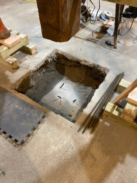
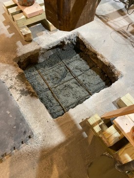
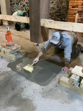
To dig my footings, I first had to bust out the old slab to create a footing pad about 30 inches square. The existing slab wasn’t that thick; it’s what some folks call a “rat slab.” It was just a couple inches thick and didn’t have reinforcing wire or rebar in it. The fill beneath the slab was something like burnt ash, and it was full of rubble and debris—plenty of broken glass, rusted cans, a few buttons, even an unbroken bottle with a cork in it below one post. It’s crazy that it never broke. As nasty as the fill was, it was relatively easy to excavate down to the bottom of the posts: a depth of about 14 inches. I tamped down the earth at the bottom of the footing holes. One had a big rock at the bottom and I drove short lengths of rebar into it to pin it to the footing. Using a stiff mix of Quikcrete 5000—a commercial-grade, high early strength concrete mix—I began filling the holes a few inches, then laid in a grid of ½-inch rebar in the lower third of the footings. Once the holes were filled, I troweled off the tops and applied a broom finish to match the existing slab.
1
of 8
Using a straightedge screwed to the column, the author made an i…
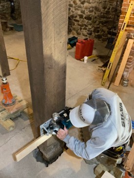
Using a straightedge screwed to the column, the author made an initial cut through the column with a circular saw.
Following the kerf line he made with the circular saw, he finis…
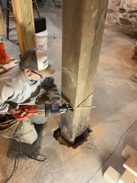
Following the kerf line he made with the circular saw, he finished the square cut with a recip saw.
The bottom ends of the columns were rotted below the slab but pe…
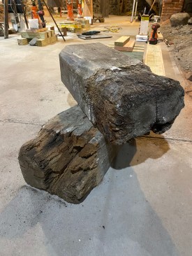
The bottom ends of the columns were rotted below the slab but perfectly sound about 2 feet above the floor.
Using a rotary hammer, the author chipped out the old slab aroun…
Using a rotary hammer, the author chipped out the old slab around the column for new footing pads.
Each footing hole was excavated to a depth of about 14 inches.
One hole had a big rock at the bottom; the author drilled into i…
One hole had a big rock at the bottom; the author drilled into it and epoxied short lengths of rebar to pin the rock to the concrete footing.
After filling the footing hole with about 4 to 5 inches of concr…
After filling the footing hole with about 4 to 5 inches of concrete, he placed a grid of rebar. This put the reinforcement near the bottom third of the excavation.
The author troweled off the top of the footing and applied a bro…
The author troweled off the top of the footing and applied a broom finish to match the existing concrete.
New Column Bases
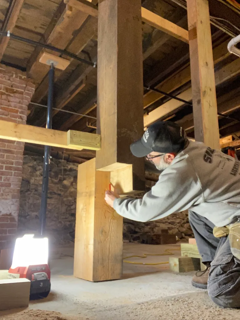
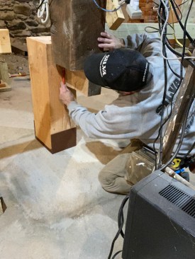
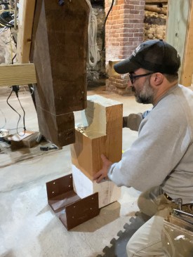
With the footings poured, I notched the ends of the existing columns to create one half of a shiplap joint to connect the new and old columns. Then, standing a 3-foot length of the new column stock next to the old column, I traced the top and sides of the notch in the old column onto the new stock and cut the matching notch.
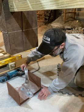
The new column sections would be secured to the slab with custom connectors I had fabricated at an iron shop from ¼-inch plate steel. As shown in the photos, these brackets have a stand-off that keeps the ends of the new column bases about a half-inch above the slab to provide some ventilation for the bottom of the timbers. Before moving forward, I checked with the town inspector. When he saw them he commented that he thought they would last forever and gave me the green light to proceed. I bolted the steel brackets to the new footings with 5/8-inch wedge anchors.
1
of 11
When notching the end of the old column to create a shiplap joi…
When notching the end of the old column to create a shiplap joint, he screwed a plastic square to the column to make horizontal square cuts.
These were finished with a long blade in his recip saw before m…
These were finished with a long blade in his recip saw before making the vertical cut to complete the notch.
A view of the finished cut.
Using wedge anchors, a custom steel column base was secured to …
Using wedge anchors, a custom steel column base was secured to the new footing pads.
The author cut through the new timbers, beginning with a square …
The author cut through the new timbers, beginning with a square cut with his circular saw.
With the new timber sitting in the steel connector (prior to bol…
With the new timber sitting in the steel connector (prior to bolting it down), he traced the notch on the old column onto the new section.
He then painted the end with an exterior primer to protect the e…
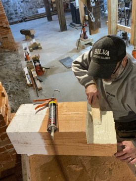
He then painted the end with an exterior primer to protect the end grain from moisture and coated all sides of the notch with a polyurethane adhesive.
The notched timber was cut slightly short to fit; galvanized ste…
The notched timber was cut slightly short to fit; galvanized steel washers slipped beneath the column will keep the joint tight.
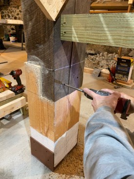
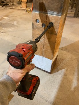
The author drilled through the shiplap joint for through-bolts.
With an impact driver, he tightened the nuts on the through-bolt…
With an impact driver, he tightened the nuts on the through-bolts.
Structural screws in the base finished the job.
After cutting the new timbers to the correct length, I painted the bottom ends with an exterior-grade oil-based primer to provide some protection from moisture wicking up through the end grain. Next, I smeared all surfaces of the shiplap joint with a polyurethane-based construction adhesive (Loctite PL Premium) and then predrilled and joined the two pieces with 3/8-inch carriage bolts extending through the entire joint to lock it together. To secure the steel bracket to the new timbers I used 3-inch-long Simpson Strong-Tie coated SDWS screws.
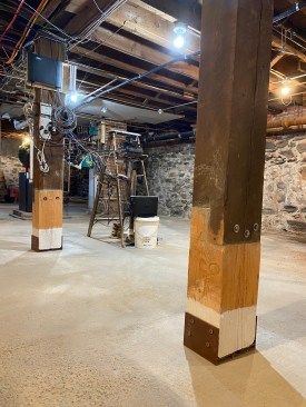
The final result passed inspection and the inspector praised my work, remarking that it was likely the repair would last another 200 years.