by Andrew P. DiGiammo
As I discussed in the previous Design column (“Making Gambrels Work,” July/August 2007, available at www.coastalcontractor.net), I’ve been interested in the gambrel form for a long time. Besides being a traditional architectural style in my area, it also offers aesthetic and practical advantages. I like roofs that spring from the first-floor wall plate, the way gambrels and capes do, rather than from the second floor. Such forms are more interesting and visually satisfying. But the gambrel has some advantages over the cape: in particular, I like how the gambrel allows me to enclose more useful space within the framed volume. And the gambrel can be very simple to frame as well.
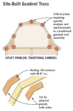
The gussets (top) in the gambrel system above (designed by the author) create a three-hinged arch out of each frame, which simplifies the load analysis significantly. Hardware is required at only three points (as opposed to nine different joints in the roof assembly of a traditionally framed gambrel), making the system considerably easier to build.
In the previous issue, I compared the traditional way of framing a gambrel — two rafter systems joined by a horizontal nailer at midroof — with a more modern method that employs gusset joints at the mid-rafter span. I examined one aspect of this roof structure: the way it handles gravity loads. As a result of new hurricane-related codes that have come into force along the East Coast, however, builders now have to determine wind loads too, which can complicate the roof design issue considerably.
The gusset system for framing gambrels is simpler than the traditional methods, and it handles the gravity-related loads as well as, or better than, the older methods. But will the system also handle wind-related loads, including lateral pressure and uplift? When I analyzed a gambrel design for wind loads, I was pleased to find the answer is yes: the gusseted gambrel is more than adequate to meet the wind-resistant construction standards that apply in my coastal area, and it’s easy to conceptualize and analyze. I won’t go into all the numbers and calculations involved, but the basic idea is outlined here.
Analyzing Traditional Framing
To understand the traditional framing system, think of the steep-sloped lower rafters as sloped walls, and think of the upper rafter pairs, connected from rafter base to rafter base by their collar ties, as a rigid triangle. In this case, even the simple gravity loads involved are really not so simple: the short, lower knee walls can get involved and bring some of the loads down to the floor, and even the floor has to be looked at for how it can handle that weight. Where the lower rafters rest on the knee walls, the rafters get placed into an odd bending situation, and they have to be looked at in terms of how they might tend to rotate around that intersection point. The whole assembly also depends on the collar tie across the ceiling, which has to be securely nailed and sized large enough so that it can restrain the spreading of the upper rafter pairs.
Throw a high wind into this picture, and you’ve got a real can of worms. Now you need to make sure that uplift on the upper roof won’t pull any of the joints apart — not at the peak and not at either elbow joint. Also, because any uplift force on the lower rafters will tend to separate the knee wall from the rafters or from the floor, you need to consider whether that joint also needs reinforcement with some sort of rated metal connector.
Analyzing the Gusset System
The gusset system relies on a pair of 3/4-inch fir plywood gussets at each joint, with the rafters sandwiched in the center. Taken together, the plywood pieces have the same thickness as the rafters themselves. As long as the joint is adequately nailed, the assembly acts as a single unit and is equivalent to a continuous sawn-lumber rafter. However, because of the angled shape and the lack of the ceiling collar tie, the rafter experiences an increased bending moment, and should be sized appropriately. In the case shown (see illustration, page 21), I have a 22-foot span and a ridge height of 11 feet, which requires a 2×12 rafter (upsized from a 2×10), with gussets extending 18 inches onto each side of the joint, nailed with 8d nails at 4 inches on-
center. These variables — gusset material and size, nailing details, and rafter sizing — will vary for each particular case in the field.
Compared with the traditional gambrel frame, this method removes almost all of the complex analysis. Using the gussets eliminates the need for the collar tie. I can now analyze the whole roof system as a simple three-hinged arch. Uplift forces create a need for reinforcement at only three points: at each of the two rafter bases where the rafters meet the walls, and at the ridge. In each case, a simple metal connector will do the job — an ordinary rafter or truss anchor at the bases of the rafters, and a metal strap across the opposing rafter tops at the peak. The numbers vary depending on your local design wind speed zone, but the bottom line is that you can use the same hardware here that you would use if the roof were an ordinary 12-pitch roof with straight rafters.
Design Philosophy
This approach conforms to my general design philosophy when in comes to the structural design of houses. I’m both an architect and a builder, and I build my own designs. Over the years, I’ve learned to consider structural aspects of the design problem early on in the process, before I commit myself to particular room layouts or building shapes. If you think about your main load-bearing assemblies and your main wind-force resisting system right at the beginning, you can design a home so that the main structural elements are easy to analyze and simple to build. By contrast, if you wait until too late in the process before you consider the structural problems, you often end up with complicated structural dilemmas that must be solved with expensive or time-consuming work-arounds.
Architect and builder Andrew P. DiGiammo owns and operates a custom design/build firm based in Assonet, Massachusetts.
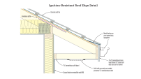
A traditionally framed gambrel (top left) requires a complicated structural analysis and extensive, labor-intensive reinforcing with metal hardware at each connection in order to direct uplift forces through the complex, multiple load paths that exist in the frame — all of which add considerable time and expense.