
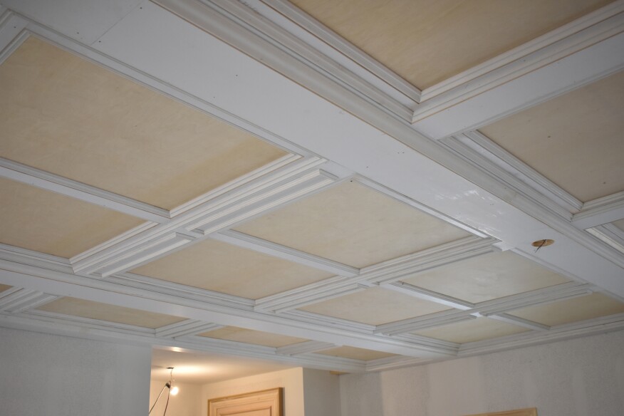
Detailed finish work on a ceiling is one of those elements that can set you far apart from other craftsmen, and it’s one of the upgrades my clients most frequently request. Over the years, I’ve developed a design that I call a paneled ceiling, which is easier to install and more adaptable to the large, open spaces in today’s homes than a traditional coffered ceiling.

Coffered ceilings typically consist of deep beams that divide the room into nine square sections with a partial beam running around the perimeter of the room. The tall sides of coffered ceiling beams can be made out of baseboard or flat finish material with panel molding added for detail. Sections of a coffered ceiling don’t have to be the same size, but they are usually close to square, which means that the room—such as an office or a formal dining room—should also be close to square for the proportions to look right.
The paneled ceiling treatment that I describe in this article will work in almost any rectangular room. It still uses major beams that run across the shortest dimension of the room, but those beams are less than half as deep as the typical coffered ceiling beams. Secondary, or minor, beams running perpendicular to the major beams divide the ceiling into rectangular sections.
Preassembled panels then fit into this beam grid and all of the layered components join together with molding. The trick is having a plan for how the layers stack in place. No two projects are exactly the same, but I like to use a printed “inspiration picture” to keep everything straight. If you need more than a picture, it might be a good idea to mock up a small corner section to see how the layers stack up where all the components meet.


Do the Initial Layout on the Floor
For a project like this, the layout is a crucial first step. I try to start the layout on the floor so I can work out the measurements and layout for the whole ceiling without needing an extra person to hold the other end of the tape. Once I am satisfied with the locations of the major and minor beams, I have someone help me transfer the measurements to the ceiling and snap chalk lines for the layout.
I always keep both red and blue chalk line on hand in case I need to tweak the layout, especially to accommodate items such as existing ceiling lights and HVAC duct vents. On this project, I could not get the layout to work with the locations of the can lights, which had been air-sealed in place with foam. So, reluctantly, we decided to abandon the cans and replace them with low-profile LED disc lights that could be attached to electrical boxes cut into the beams.

Building the Major Beams
We decided to make the beams along the perimeter of the room 5 1/2 inches wide, so we nailed 2x6s to the ceiling as the attachment layer. The major beams running across the middle of the room were 9 inches wide; for their attachment, we used two lengths of 2x4s with a 2-inch gap between them. But the major beams ran parallel to the ceiling joists, so we had to come up with a way to attach the 2x4s to the ceiling. As a solution, we installed 3/4-inch plywood nailers that spanned between the joists.
Then we needed to notch the 2x4s to fit around the plywood nailers, so we held the 2x4s in place and marked out roughly where they crossed the nailers. At the workbench, we set the depth of the miter saw blade to 3/4 inch and made several passes through the framing lumber between our marks. We removed the scrap wood and cleaned up the notch with a chisel. To mount the 2x4s on the ceiling, we first spread glue on the faces of the framing, and then tacked them to the nailers. We drove 2-inch screws at each joint to tie the assembly together.

For the final trim details to end up with the proper reveals, we had to create the correct vertical drop for the beams. The bottom surface of the beams would be 3/4-inch-thick material, and we determined that the major beams and perimeter beams would need to be padded down a total of an inch. So we added layers of 1/4-inch and 3/4-inch plywood blocking every couple of feet along all the framing for the perimeter beams and the major beams.
With the framing and padding in place, we added a layer of 3/4-inch-thick primed pine ripped to a width of 9 inches for the bottom surface of each major beam. As we nailed the pine in place, we were careful to keep it lined up with the blocking above. For the perimeter beams, we used the same material, fitting the pieces between the major beams.
Locating Lights
As mentioned before, we had to relocate the light positions. The 2-inch space between the 2x4s supporting the major beams was perfect for running electrical cable. So that each fixture would fall precisely at the intersection of the major and minor beams, we first measured out the distance from the wall to the center of the fixture. Next, using a 4-inch hole saw, I carefully drilled the hole in the pine board for the pancake electrical box. (Our electrician assured us that pancake boxes would be adequate for the low-profile LED fixtures). We then fastened the board in place with the supply wire led through the drilled hole.

Building the Panels
The next step was building the ceiling panels. My design called for the frames for each panel section to be 3 1/2 inches wide and made from 3/4-inch pine. I planned to space the panels 2 inches from the major beams and from the wall beams, so we marked the layout from the major beams and perimeter beams with a 2-inch block. The minor “beams” would also be 3/4-inch pine, but would be 5 1/2 inches wide; they would bridge between the panel sections and lap over them by 1/2 inch. That meant that we needed to leave a 4 1/2-inch space between the panel sections, which was the spacing of the lines we’d snapped on the ceiling earlier.
After taking careful measurements, we started building the frame-and-panel sections. We made single-panel sections for the ends of the room and double-panel sections for the middle of the room. We cut all the parts for the frames using a miter saw with a very accurate stop system for fast, repetitive cuts that made the frames identical. I ripped the frame pieces from wider boards and I ran them on edge through a planer to ensure that they were all exactly the same width.
For speed and strength, I used pocket-screw joinery to assemble the frames, and then glued and stapled 1/4-inch plywood to the back of each frame for the panel faces. We trimmed the inside edges of each panel with a Kuiken Brothers panel-molding profile (KB 242). Because the frames were identical, I cut the panel molding to fit inside each frame using the same stop system on the miter saw, and then glued and nailed the pieces in place with headless pins.
Setting the Panels
At this point, we had the major beams completed to the bottom surface along with the perimeter beams that ran parallel to the major beams. The design called for a run of single-width panels between the perimeter beam and the first major beam, so we filled in that run of single panels starting at one end of the room and installing them on our layout lines.
Working overhead, a second crew member was a huge help holding the panels against the ceiling while I aligned and fastened them. This was especially true with the double-width panels that were heavier and more unwieldy. Positioning the panels in both directions was also tricky, but wherever possible, I used a spacer to keep the panel positioned in one direction while I lined up the panel in the other direction and nailed it through the ceiling drywall and into the joists.

The In-Between Layer
Next, we had to add the layer of finish that stepped down from the frame of the installed panels to the bottoms of the major beam. As with the previous layers, this intermediate layer was made of 3/4-inch pine. Along the major beams, this layer was a strip of pine 2 1/2 inches wide. When butted against the framing for the major beams, the strip overlapped the panel frame by 1/2 inch.
Before we could install this strip, we needed to install blocking for nailers in the space between the panels and the major beams. We ripped 1-inch material for the nailers that was equal to the total thickness of the panels: 3/4 inch for the pine frame plus the 1/4-inch plywood stapled on back. We installed the nailers every couple of feet, gluing and tacking them in place.
After the nailers were in place, we put in our 2 1/2-inch-wide strips of pine parallel to the major beams and lapping onto the panel frames. Because we could not get material long enough for entire runs of the 3/4-inch stock, we used 45-degree scarf joints to add the extra length. We located each scarf joint at a nailer, carefully gluing and nailing in the filler pieces.
To complete the intermediate layer, we added the 5 1/2-inch-wide minor-beam pieces that fit between these strips. These pieces also lapped 1/2 inch onto the panel frames. To make the minor-beam pieces perfectly in plane with the 2 1/2-inch strips, we flushed them at each corner and drove pins to hold them even. At the end walls, where there were no minor beams, we simply ran additional 2 1/2-inch strips between the strips along the major beams.

Add the Trim
With a project like this, I am always anxious to see what a finished section will look like. It probably isn’t the most productive way to work, but I feel like a kid on Christmas morning, so I had the crew jump ahead and install the moldings to finish the first sections we had installed.
We used two runs of molding to complete each paneled section. Working down from the ceiling, the first run of molding sat below the paneled frames and butted against the edges of the 2 1/2-inch strips in one direction and against the minor beams in the other direction. For this run of molding, we used the same panel molding profile that we’d used on the panels.
The second molding layer was actually a bed molding profile (KB 319) that nailed to the edge of the major beams at the bottom and butted against the face of the 2 1/2-inch strips at the top. With the material thickness and blocking, there was a 1 1/2-inch difference in height between the two layers. To create a 1/8-inch reveal at the bottom of the bed molding, I chose a profile with a height of 1 3/8 inches.
This height worked fine for most of the ceiling except in one area where the ceiling height dropped slightly, making the reveal disappear. Because that bottom reveal is critical to the visual success of the molding, I scribe-fit the molding in this area, planing enough off the top of the bed molding to maintain an even reveal. The difference at the top of the bed molding was barely noticeable, and I was then able to nail in the molding in place with none but the sharpest eyes able to pick up on the tweak that I’d made.
I’ve occasionally been accused of gilding the lily, and the paneled ceiling would have been fine with the bottom surfaces of the beams left unadorned. But I opted to dress up the minor beams with surface-applied panel molding (KB 654). We cut and built the rectangular assemblies on the workbench, gluing and pinning the joints. We had to cut only two lengths of panel molding, so we mass-produced the pieces for these assemblies using the stop system on the miter saw. Next time I do a paneled-ceiling project like this, I may try attaching the panel molding to each minor beam section before it is nailed into place. This time around, we just measured carefully to make sure everything lined up before we nailed anything in.
All photos by Bryan Striegler.


