|
Editor’s Note
In August 2003, we ran the article “Attaching Deck Ledgers,” in which authors Cheryl Anderson, Frank Woeste, and Joe Loferski presented fastener schedules based on code-referenced structural design methods. Though the number crunching was accurate, some of the bolt and lag spacings seemed impossibly conservative, as both the article and several follow-up letters pointed out. Even before the article reached your mailbox, Joe Loferski and Frank Woeste had agreed to build samples of the ledger-to-band-joist connections and test them in the wood science lab at Virginia Tech. The tests would show how theoretical structural connections designed using engineering formulas compared with the actual connections, tested to destruction under code loads. As promised (Letters, 11/03), here are the results. You’ll find them a little more builder friendly. Many thanks to Joe, Frank, and team for undertaking this important work. Unfortunately, just as we bring greater focus to one area of deck construction, another issue has reared its head — the corrosive nature of the new pressure-treating chemicals coming onto the market. Extensive testing by connector manufacturer Simpson-StrongTie has shown the new treatment formulations to be more than twice as corrosive to hardware as the CCA treatment that is being pulled from the market. We plan to look more closely at this issue in the future; for now, it’s best to play it safe when working with the new pressure-treated lumbers and stick to minimum G185 galvanized hangers and hot-dipped fasteners, or stainless-steel hangers and fasteners. Do not mix stainless with galvanized. For more information, see the box at the end of the article.–Don Jackson |
Introduction
In the article “Attaching Deck Ledgers” (8/03), the authors used a procedure from the National Design Specification for Wood Construction (NDS-2001) to calculate the required on-center spacing of lag screws and bolts for deck-ledger-to-band-joist connections for various deck widths. Although the calculated spacings were “to code,” they were too tight to be practical. The reason is that the NDS limits the allowable load for lag screws and bolt connections based on a very small “deformation” at the design load — a deformation limit intended to prevent undesirable movement of a wood-framed structure and to prevent finishes such as tile and drywall from cracking.
The purpose of this article is to report the results of load tests conducted on four connection details that could be used to connect a residential deck ledger board to the house band joist. Using this test approach, which is recognized by the code, we found that the “allowable” loads for lag screws, for example, are two to three times higher than the values obtained using the NDS-2001 equations. Bolts proved to be even stronger compared with NDS-designed connections.
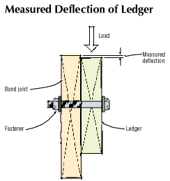
The deflection of the ledger relative to the band joist was measured at full design load. The range of deflections for the 15 samples of each detail tested is noted, so that the deck designer can judge whether the expected displacement is acceptable.
Code Allowance for Load Testing
The International Building Code (IBC, 2000 and 2003 editions), as well as previous codes, allows for load testing when “a construction is not capable of being designed by approved engineering analysis” or “does not comply with applicable material design standards.”
In the case of deck ledger connections to the main structure, the minimum required fastener penetration of a lag screw into the house band joist is four times the fastener diameter (4D). This requirement cannot be met when you use 1/2-inch-diameter lag screws to attach the ledger to the band joist, because a typical band joist is only 1 1/2 inches thick (3D), not the required 2 inches thick (4D). Even if the band were 2 inches thick, the 1/2-inch lag screw values in the NDS-2001 tables must be reduced by half because they are based on lag screw penetration into the main member (the band joist) of eight diameters (8D), or 4 inches.
Similarly, there are no available tables for designing a bolted ledger employing drainage spacers, or even for a ledger attached on top of structural sheathing (the NDS assumes the connected members are in direct contact).
Therefore, we tested simulated ledger-to-band connections and calculated allowable on-center spacings based on the ultimate capacity of the connection, applying a safety factor and an adjustment for load duration. The test load duration was about five minutes, whereas the assumed duration for an occupancy live load (40 psf for deck or 60 psf for balconies) is ten years.
Code Language on Decks
Note that the International Residential Code (IRC 2003, R502.2.1 Decks) states: “Where supported by attachment to an exterior wall, decks shall be positively anchored to the primary structure and designed for both vertical and lateral loads as applicable. Such attachment shall not be accomplished by the use of toenails or nails subject to withdrawal….”
This section means that nails alone cannot be used to connect a ledger to a band joist when no other lateral bracing is in place to positively anchor the deck to the building against lateral loads. Thus, in the absence of adequate lateral bracing, lag screws, bolts, or some other positive connection will be required to design and build a code-compliant deck.
Test Setup
For the test, we fabricated specimens from 2×10 No. 2 spruce-pine-fir (SPF) lumber to simulate the band joist of the house. These were attached to a 2×8 No. 2 CCA-pressure-treated southern pine (SP) ledger board sample. We used either 1/2-inch-diameter lag screws or 1/2-inch-diameter bolts for all tests. Some specimens included 15/32-inch APA-rated plywood to simulate the gap produced by conventional wall sheathing between the ledger and band joist. One test case included a 1/2-inch stack of washers between the ledger board and the plywood to replicate the drainage space sometimes incorporated into the connection, a practice shown in some deck design books and in past JLC articles.
The 2-by band joist was supported on the testing machine base to simulate direct bearing on the foundation sill plate.
The CCA-pressure-treated sample deck components consisted of two 2×8 joists attached to a 2×8 ledger with joist hangers. We used extra fasteners to attach the joist hangers to the ledger to ensure that failure would occur in the lag screw or bolt connection. The far end of the deck joists were supported on solid spacers on the base of the testing machine.
We realize that CCA-treated lumber is now restricted in residential applications, but at the time of the testing, we needed to include an unseasoned (wet) ledger as part of the test, and CCA was locally available. After testing, we verified that the ledger material was “green” — that is, having a moisture content well above 19%. By using unseasoned ledgers in our tests, we had no need to apply an adjustment to our test results for “wet service use.”
On the specimens that included sheathing, the plywood was trimmed so it was 2 inches shorter than the width of the ledger board to prevent it from accidentally bearing on the test platform and artificially inflating our tested lag or bolt connection.
A universal hydraulic testing machine applied the load, at a constant rate of 1/2 inch of deflection per minute. The deflection was measured by an electronic transducer attached to the ledger board in such a way that it measured the vertical displacement of the ledger board relative to the band joist. During testing, the load and displacement data were continuously recorded by a computer.
The load was applied to the specimen at the center of the joist, and the load measured by the testing machine was divided by two to account for the reaction at the opposite end of the joist. In other words, half the load was applied to the connection itself, and half the load was applied to the foundation at the opposite end of the joists, just as in a real deck. The load was applied until the connection failed to carry any additional load.
Lag Screw and Bolt Installation
We followed the rules prescribed in NDS-2001 for fastener installation as they relate to clearance, lead-hole diameters, and use of washers. For lag screws, two hole diameters are specified, a slightly larger clearance hole to allow the nonthreaded portion to penetrate the side member (ledger) without splitting and a smaller lead hole in the main member (band joist) to fully engage the threads.
We purchased 1/2-inch-diameter lag screws from a local building supply store and measured the root diameter of the threaded portion of the screws. The root diameter was 0.39 inch, so we used a 3/8-inch lead hole, which is slightly smaller than the root diameter, to accommodate the threads of the lag screw in the band joist. We used a 1/2-inch clearance hole in the CCA-treated ledger board to accommodate the nonthreaded portion of the shank. We tightened the connections normally, by hand with a wrench. In general, when installing lag screws, you should feel significant turning resistance; otherwise, the lead hole may be too large. Washers were not used under the lag screw heads because NDS does not require them. However, we believe that a washer on a lag screw will improve the connection, and we would use them on our own projects for added safety.
For the bolted connections, the NDS-2001 requires the holes to be a minimum of 1/32 inch to a maximum of 1/16 inch larger than the bolt diameter. Therefore, we drilled 9/16-inch holes in both the ledger board and the band joist to accommodate the 1/2-inch bolts. We added washers on both sides of the bolt connections as specified by NDS: one between the head and the lumber, and the other between the nut and the lumber.
Four Cases Tested
We tested four different cases to represent common construction practices. Fifteen replications of each case were tested. Case 1 included a 2×8 SP ledger attached to a 2×10 SPF band joist with a 3.5-inch-long by 1/2-inch-diameter lag screw. Note that we used a 3.5-inch screw, because the tip of a lag screw is not effective in load transfer. Case 2 incorporated the 2×10 SPF band joist and 2×8 SP ledger with a 15/32-inch plywood spacer to simulate the wall sheathing commonly sandwiched between the ledger board and the band joist. We connected the ledger to the band with 4-inch-long by 1/2-inch-diameter lag screws. Case 3 included the 2×10 SPF band joist, 2×8 SP ledger, and the 15/32-inch plywood layer, connected with a 1/2-inch-diameter bolt with washers. Case 4 was similar to Case 3, except that we added a 1/2-inch stack of washers — the drainage space — between the plywood and ledger to simulate a nearly 1-inch gap (including the plywood) between the ledger and the band joist.
Case 1: 1/2-Inch Lag Screw
The tested deflection of the ledger relative to the band joist at design load (50 psf) ranged from 0.03 in. to 0.17 in. LimitationsLumber sizeThis schedule is valid only for 2×8 or larger ledgers with a specific gravity, G, of 0.55 or greater (G for southern pine = 0.55) and 2-by band joists with G of 0.42 or greater (G for SPF = 0.42). Lumber typeTabulated fastener spacings are based on virgin lumber with no decay. Flashing must be properly applied to keep water from penetrating the joint and wetting the untreated band joist. The deck ledger must be pressure treated with an approved chemical and retention. In the case of new home construction, a pressure-treated house band in the deck area is recommended. LoadsThe tabulated spacings apply to residential decks (40-psf live load, 10-psf dead load) and do not apply to residential balconies (60-psf live load) or other applications having design loads greater than 40-psf live load plus 10-psf dead load. Lag screw installationThe results apply only to 1/2-inch-diameter lag screws long enough to fully penetrate the band joist, not counting the tapered lag screw point. Lead holes in the band joist for lag screws must be drilled slightly smaller than the root diameter of the threads, so that the threads fully engage the main member. The clearance hole in the deck ledger must be drilled to the same diameter as the nonthreaded shank. Lag screws should be staggered to guard against splitting. Joist configurationThe tabulated spacings apply to deck construction where the joists are laid out 24 inches on-center or less and run perpendicular to the ledger. The spacings do not apply to deck construction where the deck joists are parallel to the ledger and joist loads are transferred to the ledger using widely spaced girders. That produces a large concentrated load on the ledger; in that case, design by a professional is required. InspectionDeck framing and connections should be inspected annually to detect possible deterioration. |
The tested deflection of the ledger relative to the band joist at design load (50 psf) ranged from 0.08 in. to 0.24 in. LimitationsLumber sizeThis schedule is valid only for 2×8 or larger ledgers with a specific gravity, G, of 0.55 or greater (G for southern pine = 0.55) and 2-by band joists with G of 0.42 or greater (G for SPF = 0.42). Lumber typeTabulated fastener spacings are based on virgin lumber with no decay. Flashing must be properly applied to keep water from penetrating the joint and wetting the untreated band joist. The deck ledger must be pressure treated with an approved chemical and retention. In the case of new home construction, a pressure-treated house band in the deck area is recommended. LoadsThe tabulated spacings apply to residential decks (40-psf live load, 10-psf dead load) and do not apply to residential balconies (60-psf LL) or other applications having design loads greater than 40-psf live load plus 10-psf dead load. Lag screw installationThe results apply only to 1/2-inch-diameter lag screws long enough to fully penetrate the band joist, not counting the tapered lag screw point. Lead holes in the band joist for lag screws must be drilled slightly smaller than the root diameter of the threads, so that the threads fully engage the main member. The clearance hole in the deck ledger must be drilled to the same diameter as the nonthreaded shank. Lag screws should be staggeredto guard against splitting. SheathingThe test results apply to wall sheathing thicknesses of 15/32 inch or less. Joist configurationThe tabulated spacings apply to deck construction where the joists are laid out 24 inches on-center or less and run perpendicular to the ledger. The spacings do not apply to deck construction where the deck joists are parallel to the ledger and joist loads are transferred to the ledger using widely spaced girders. That produces a large concentrated load on the ledger; in that case, design by a professional is required. InspectionDeck framing and connections should be inspected annually to detect possible deterioration. |
The tested deflection of the ledger relative to the band joist at design load (50 psf) ranged from 0.11 in. to 0.35 in. *These spacings have been reduced from the allowable value determined by testing in consideration of the ledger’s bonding strength between bolts. LimitationsLumber sizeThis schedule is valid only for 2×8 or larger ledgers with a specific gravity, G, of 0.55 or greater (G for southern pine = 0.55) and 2-by band joists with G of 0.42 or greater (G for SPF = 0.42). Lumber typeTabulated fastener spacings are based on virgin lumber with no decay. Flashing must be properly applied to keep water from penetrating the joint and wetting the untreated band joist. The deck ledger must be pressure treated with an approved chemical and retention. In the case of new home construction, a pressure-treated house band in the deck area is recommended. Bolt installationThe results apply only to 1/2-inch-diameter bolts of sufficient length to allow for a washer under the head and a washer under the nut. Holes for bolts must be drilled 1/32 to 1/16 inch larger than the bolt diameter. Bolts should be staggered to guard against splitting. SheathingThe test results apply to wall sheathing thicknesses of 15/32 inch or less. Joist configurationThe tabulated spacings apply to deck construction where the joists are laid out 24 inches on-center or less and run perpendicular to the ledger. The spacings do not apply to deck construction where the deck joists are parallel to the ledger and joist loads are transferred to the ledger using widely spaced girders. That produces a large concentrated load on the ledger; in that case, design by a professional is required. InspectionDeck framing and connections should be inspected annually to detect possible deterioration. |
The tested deflection of the ledger relative to the band joist at design load (50 psf) ranged from 0.25 in. to 0.42 in. *These spacings have been reduced from the allowable value determined by testing in consideration of the ledger’s bonding strength between bolts. LimitationsLumber sizeThis schedule is valid only for 2×8 or larger ledgers with a specific gravity, G, of 0.55 or greater (G for southern pine = 0.55) and 2-by band joists with G of 0.42 or greater (G for SPF = 0.42). Lumber typeTabulated fastener spacings are based on virgin lumber with no decay. Flashing must be properly applied to keep water from penetrating the joint and wetting the untreated band joist. The deck ledger must be pressure treated with an approved chemical and retention. In the case of new home construction, a pressure-treated house band in the deck area is recommended. LoadsThe tabulated spacings apply to residential decks (40-psf live load, 10-psf dead load) and do not apply to residential balconies (60-psf LL) or other applications having design loads greater than 40-psf live load plus 10-psf dead load. Bolt InstallationThe results apply only to 1/2-inch- diameter bolts of sufficient length to allow for a washer under the head and a washer under the nut. Holes for bolts must be drilled 1/32 to 1/16 inch larger than the bolt diameter. Bolts should be staggered to guard against splitting. SheathingThe test results apply to wall sheathing thicknesses of 15/32 inch or less. SpacersWhere spacers are used for drainage, the gap between the ledger and the wall sheathing created by the spacers must be 1/2 inch or less. Joist configurationThe tabulated spacings apply to deck construction where the joists are laid out 24 inches on-center or less and run perpendicular to the ledger. The spacings do not apply to deck construction where the deck joists are parallel to the ledger and joist loads are transferred to the ledger using widely spaced girders. That produces a large concentrated load on the ledger; in that case, design by a professional is required. InspectionDeck framing and connections should be inspected annually to detect possible deterioration. |
Safety factor applied. To determine allowable fastener spacings, we calculated the maximum average load for each case and reduced the results by factors to account for safety and the fact that the laboratory tests were of short duration.
The IBC requires that failure loads from tests of structural assemblies be divided by a safety factor of 2.5. For the purpose of decks, we used an even larger safety factor, of 3.0, to further account for possible variations in field installation of lag screws and bolts.
The average maximum load was further reduced by a load duration factor of 1.6 to account for the difference in performance between short-term laboratory testing (about five minutes) and ten-year continuous loading as defined for occupancy live load in the NDS.
Wet-use factor not needed. The NDS requires a “wet-use” reduction factor (Cm ) to be applied to connection design values for situations where the wood is expected to be above 19% moisture content. For those tests, we used wet CCA-treated southern pine ledger boards, with an average moisture content of 44%. Because we expect the moisture content of deck lumber to remain above 19% during periods of wet weather, we applied no reduction in the calculated design strength; the effect of using wet lumber is included in the test.
Deck loads. After applying these reduction factors, the resulting values were used to calculate the required spacing between fasteners for various joist spans based on a design loading of 40-psf live load and 10-psf dead load, as specified in the IRC for residential decks. However, because residential balconies have a higher design load than residential decks, these spacing results do not apply to balconies.
Failures of Lag Screws vs. Bolts
The fastener spacings for the bolted connections (Cases 3 and 4) are considerably larger than for those of the lag screws (Cases 1 and 2). At high test loads, the washers under the head and nut keep the bolt from withdrawing completely from the connection; thus the ultimate loads for the bolted specimens were generally greater. For lag screw specimens, failure often occurred when the threaded shank withdrew from the band joist or when the head of the lag screw embedded itself into the ledger. Also, due to the threads, lag screws have a reduced diameter in the band joist, and thus the screw rotates more easily under load than a bolt of the same nominal size.
Expected deformations. The tables include the measured range of vertical deformation between the band and the ledger for each case. These numbers provide an estimate of the expected range of deformation at full design load for a short period of time. If the live load on a deck is sustained — for instance, from heavy planters — this expected deflection of the ledger relative to the band joist may be double the stated figure, or even greater. Judgment is needed in using this data for particular cases of significant sustained live loads. Occupant loading on a deck is not considered sustained.
Limitations of Results
The strength of mechanical connectors used in wood construction depends partly on the specific gravity, G, of the lumber. Southern pine, the ledger material we used, has a G of 0.55; SPF, the sample band joist, has a G of 0.42.
The main disadvantage of this test-based approach is that the allowable values cannot be extrapolated downward for materials having a lower strength. For example, we cannot use the test data to predict the strength of a lag screw connection made with a pressure-treated hem-fir ledger (G = 0.43). It would be acceptable to use the schedules with a hem-fir band joist, however, as long as the ledger was southern pine.
Joe Loferski and Frank Woeste, P.E., are professor and professor emeritus, respectively, in the Department of Wood Science and Forest Products at Virginia Tech University, Blacksburg. Ricky Caudill is a lab technician, Terry Platt a research scientist, and Quintin Smith a summer intern in the department. At the end of April, Drs. Woeste and Loferski will conduct a short course entitled Liability Issues, Design Data, and Inspection Techniques for Wood Decks, Balconies, and Porches. To learn more, visit www.conted.vt.edu/sdww.
For More InformationTo read more about the corrosiveness of the new pressure-treating chemicals, go to www.strongtie.com/ftp/bulletins/TPTWOOD04.pdf. |


