

When it came time to build a “forever” home for my family, I drew on the experience gained over my 15-year career as a project manager for several commercial general contractors and later as the owner of a subcontracting company that erects large-scale, wood-framed buildings for hotels and apartment complexes. For example, in lieu of a traditional wood-framed floor system, I designed our home to have a podium concrete-slab floor system on the main level supported by structural steel and metal “B” Deck over a walk-out basement, a construction technique that we often use on commercial structures. When we started this project, our kids were in their early teenage years, and we wanted a solid floor system to help reduce the impact sound they made when they were running throughout the house.
This structural feature—more typical of commercial construction—allowed us to be creative with the design of the stair system to the ground-level floor where the kids’ bedrooms would be located. We wanted the stairs to feel like an appealing feature of the house, and not be just a door to the basement. The challenge was that the open staircase we had in mind was designed on a radius; subcontracting it out was beyond our budget.
Having experience building radius walls with bar-and-latch-type concrete forms (advanceconcreteform.com), I knew we could build the stairs more economically out of concrete using in-house carpentry labor. This became the basis of our stair design: a concrete staircase with bluestone treads and natural stone risers. As an added benefit, the area below the stairs would also act as a safe room.
Footing and Forms
Our first step was to form and place a 1-foot-thick footing below the entire stair system to support the estimated 61,800 pounds of the assembly. After the concrete cured, we started forming the full-height curved walls for the staircase, which has a 4-foot 4 3/4‑inch inside radius and an 8-foot 6 3/4-inch outside radius.

Forming the walls. We positioned the forms for 8-inch-thick walls following layout lines that we had marked on the footing, using two ties (instead of the normal one) per latch. As we installed the forms, we were able to latch the inner wall forms together, but we left the outer wall forms unlatched. Then we divided the number of gaps in the outer forms by the combined width of all the gaps. This provided us with a consistent dimension for our wood filler strips, which we ripped out of 2-by material, beveling the cuts to a 10-degree angle for a tight fit between forms. As we inserted the filler strips, we used 1/2-inch clips instead of latches to join the forms together, with two clips in place of each latch. Then we installed blocking bridges over the wood strips to hold the panels together.


At the top of the radius wall, we formed steps, which were needed so that the structural steel supporting the floor system would “fly over” this wall. The radius wall was designed to carry the load of the stairs only and not of the floor above. In podium construction, all of the house loads are carried by the first-floor slab over the Type B metal deck supported by structural steel, which transfers those loads to steel columns and the perimeter foundation walls.


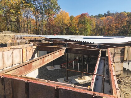

Forming the stair opening. Once the structural steel and Type B metal deck structural substrate were assembled, we needed to create the stair opening, which would cantilever past the vertical plane of the large radius wall and the steel. For this, we infilled and formed the opening with temporary partition walls, wood joists, and plywood. Then we placed the concrete for the structural slab floor.
Radius stem walls. Next, we formed the radius stem wall on the open side of the stairwell along with the stair steps in preparation for a monolithic concrete placement. The layout needed to comply with a couple of IRC sections for winder treads; one is R311.7.4 Walkline, which states: “The walkline across the winder treads shall be concentrated to the curved direction of travel through the turn and located 12 inches from the side where the winders are narrower.” The other relevant code section is R311.7.5.2.1 Winder Treads, which states: “Winder treads shall have a depth of not less than 10 inches measured between the vertical planes of the foremost project of adjacent treads at the intersections with the walkline.”
Once we had determined the layout, we snapped lines on the floor and also vertically on the concrete walls so that the layout would stay true when we were ready to form the steps against the full-height wall. We cut the baseplates and top plates out of 1-inch-thick AdvanTech sheathing and fastened the baseplates to the concrete floor with Tapcons.

We built three temporary partition walls to act as forms for the treads and for the stem wall that would terminate below the concrete mass for the stair system itself. We constructed the innermost wall full height to allow for the narrowest part of the stair treads to be cantilevered over the stem wall so that the stone façade in the lower floor level would have a termination point. Then we built the two partitions for the stem wall, with 2x4 studs located 6 inches on-center.


To sheathe the partition walls to make the forms, we first applied 1/2-inch plywood to the inner face of the small inner partition below the stairs. Then we temporarily removed the system off the bottom plate so that we could sheathe the inner face of the other partition wall and wrap the full-height wall with plywood. Then we dropped the small partition back into position.
We transferred the locations of our tread ends to the vertical walls and formed the underside of the stair system 8 inches below the bottom of the tread forms. We anchored the tread forms to the partitions and the concrete wall, applied form release to all surfaces, and then drilled and epoxied #5 rebar into the full-height concrete walls.
Placing the Concrete
When laying out the forms, we paid close attention to IRC Section R311.7.5.1, which notes that “the greatest riser height within any flight of stairs shall not exceed the smallest by more than 3/8 inch.” Knowing this, we had to be as accurate as possible with the placing and finishing of the concrete.
We ordered a 4,000-pound, small-stone concrete mix with a 5-inch slump for the pour. To eliminate voids, we carefully and thoroughly vibrated the poured concrete, starting at the bottom and working our way up as we placed it. In all, the stairs and pony wall took about 4 1/2 yards of concrete.

The next morning, we removed the risers before the formwork had a chance to swell and become very difficult to remove. Then we waited another day to strip the temporary walls.


Finish Treads
We purchased 2-inch-by-18-inch-by-6-foot thermal bluestone treads (Ghent Wood Products) and used a demo saw guided by a straight 2x8 to cut them to size. Because we would be facing the risers and walls with natural stone, we had generous tolerances for making these cuts.
We set the treads with landscaping adhesive, using a laser level for reference and placing plastic shims as needed to ensure the treads were within tolerance. We began with the uppermost tread, for which we had formed a recess notch in the upper floor slab. This allowed us to set the tread so that it would be flush with the porcelain-plank-tile finish floor. Then we worked our way down, chipping away the occasional glob of concrete “snot” as needed. After the treads were placed, we sealed them with Miracle Sealants 511 Impregnator Sealer, followed by Behr Wet-Look Sealer.


Balustrade
We anchored Azek trim boards to the edge of the stair opening in the upper slab and the stringer of the open side of the stairwell with Tapcons, then patched the holes with Bondo. We didn’t need to use heat blankets on this project to make the Azek more pliable but would recommend them if it needed to be bent to a tighter radius.
I had spent many months grappling with the question of how to build a baluster and railing system for a lower cost after receiving quotes in the neighborhood of $25,000 for a traditional wood railing system. But then I remembered a house that I had grown up in that my father had built that had a steel cable for a railing system. After some online research, I found Westech Rigging (now known as Bishop Lifting), which carries the perfect cable rail for this application: 1 1/4-inch-diameter swaged wire rope with a smooth edge, commonly used in the logging industry.
More research to find all the other components, such as newel posts, balusters, and baluster brackets, led me to DJA Imports. The biggest challenge was figuring out if we were going to anchor the balusters directly into the porcelain tile and bluestone or use some other method. After searching DJA’s website and grappling with this step, we landed on cast-iron side-mount baluster brackets with a 3/8-inch-diameter female thread on the back of the flange for attachment into the stringers and upper landing. For the newel posts, we used a two-piece cast-iron product, also from DJA. For the balusters, we found wrought iron, 9/16-inch-diameter round pickets on clearance at DJA for $8.03 per piece.


Assembly. When we installed the newel posts, we had to take care that they were on the correct plane so that the side-mount brackets and cable handrail would land in the center of the newel posts. Knowing that welding cast iron is difficult, we decided to join the two components of the posts together with epoxy, then fill the posts with concrete and two pieces of #4 rebar. With the rebar protruding out of the bottom, we let them cure upside down. We then drilled holes into the bluestone and concrete slab to accept the rebar, and set the posts with DeWalt AC100+ Gold Quik-Shot two-part acrylic epoxy adhesive.
The next step was to lay out and install the side-mount brackets. For the upper landing, we used a laser to mark out a horizontal line and marked every 4 inches on-center. We then drilled 3/8-inch-diameter holes through the Azek and concrete for 3/8-inch-diameter-by-6-inch lengths of threaded rod. We assembled the threaded rod into the back of the side-mount flanges, injected the drilled holes with DeWalt epoxy, and inserted the side-mount brackets into the holes, using a laser to ensure that the brackets were plumb.
Handrail. To make sure we cut the wire rope to the correct length, we first used a 1/8-inch-diameter wire cable as a template, laying it across the brackets and holding it in place with clamps. We marked the centers of the brackets on the cable so that the marks could be transferred to the wire rope.
Knowing that steel can’t be welded to cast iron, we planned to attach the wire rope to the newel posts by cutting it 3 inches longer on each end and then cutting back 3 inches of the outer core at the ends, leaving the center core of the wire cable intact. Then we could insert the center core into a hole drilled into the concrete-filled cast-iron newel post.
Logger’s cable/wire rope is manufactured and shipped with grease, which must be removed before installation. While we hand-sprayed the rope repeatedly with mineral spirits and wiped it down, it would have been better if we had soaked the cable to remove the grease inside the core. We discovered this problem later when welding the balusters to the rope, which resulted in small puddles of melted grease.
Balusters. The cast-iron side-mount brackets had some variation in the baluster pockets. On the upper landing, we set up a laser to the correct height of where the bottom of the wire-rope handrail would be located and measured, numbered, and cut each baluster to its correct height. After injecting the newel posts with epoxy, we inserted the ends of the wire rope into them. We supported the heavy cable at the proper height by placing a baluster every 2 feet or so, clamping the balusters to the wire rope and securing their bottom ends into the side-mount brackets using epoxy.


We followed the same procedure when installing the handrail on the stairs, though we also had to twist the rope to make the curve up from the lower newel to the upper one. Then we welded the balusters to the wire rope, following the lines that we had marked with the help of our 1/8-inch-diameter template.
After cleaning up the welds with an abrasive flap disk mounted in an angle grinder, we applied a thin epoxy overcoat by hand. Then we primed and painted the railing system. Instead of spraying the finish on, we used a sock to apply one coat of Sherwin-Williams Pro-Cryl Universal acrylic primer, and two finish coats of its DTM Acrylic Coating in semi-gloss black.
Finally, we applied natural, 1 1/2-inch-thick stone veneer from Chippewa Stone to the risers and walls.
Photos by Janette Meppen


