Glenn Mathewson
A roof with a ridge beam can be more easily understood if it's i…
Long before any building codes were published, conventional roof framing methods developed through practice, resulting in approaches to roof framing that are as varied as the framers themselves. In the past, methods described by the three main building codes (BOCA, UBC, and SBC), though similar, differed based on climatic factors—such as expected wind and snow loads—local habits, and available materials. Between the Eastern and Western codes, there were even different names for identical parts. Combining these disparate styles and standards into a single code—the International Residential Code (IRC)—was no easy feat, and seemingly fundamental aspects of roof construction are still up for debate.
Understanding this history provides perspective on why the treatment of roof construction in the IRC and the associated Wood Frame Construction Manual (WFCM) allows for such broad interpretation. But when it’s boiled down, there are essentially two standard methods of roof construction, each having some flexibility. They’re most easily identified by the type of ridge used: either a ridge beam, which is a structural or load-bearing member, or a ridge board, which is a non-structural framing member. The rest of the roof framing then follows suit.
Framing with A Ridge Beam
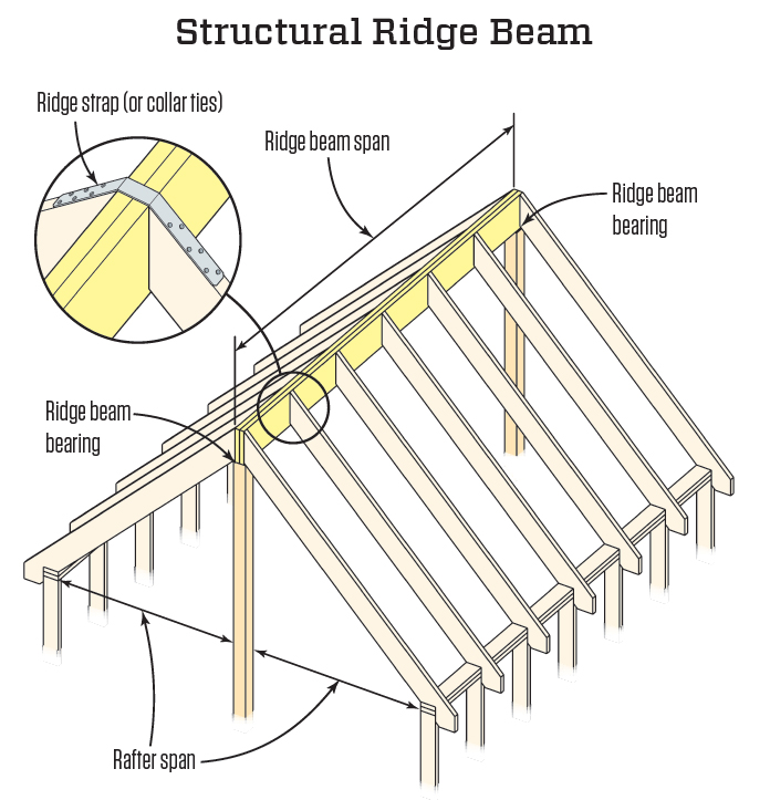
A roof with a ridge beam can be more easily understood if it’s imagined to be a flat surface—like a deck in plan view. The ridge is constructed as a beam that runs from end to end. The ends of the beam must be supported as concentrated loads, generally by posts inside walls or in the middle of a room. The rafters are then connected to the beam and transmit their full vertical load downward. Again, picture deck joists connected to a beam with hangers. The other ends of the rafters bear on the exterior walls.
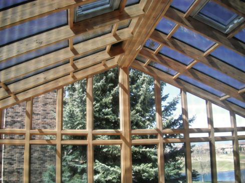
In an actual ridge-beam roof—rather than in our imaginary flat surface—the center beam can be raised to any height (see Structural Ridge Beam illustration), creating a vaulted ceiling below without an attic space (although the code does allow for building an attic by adding properly sized ceiling joists). The ridge-beam approach is simple except for the sizing of the beam, for which the IRC does not provide guidance. Using an engineered beam (such as an LVL) for the ridge is helpful in this regard because large spans can be achieved and span tables are usually available from the manufacturer.
In ridge-beam roof construction, the connection of the rafters to the ridge must handle the entire gravity load on the rafters. In most cases that connection is achieved with manufactured load-rated hardware. However, the IRC does allow a prescriptive wood-to-wood connection of the rafters to the ridge for slopes of 3:12 and greater. Table R602.3(1) requires that either four 16d toenails or three 16d end nails be used for the connection. But when using this nailing schedule, keep in mind that uplift must still be addressed using either collar ties or ridge straps (more on that later).
Framing with A Ridge Board
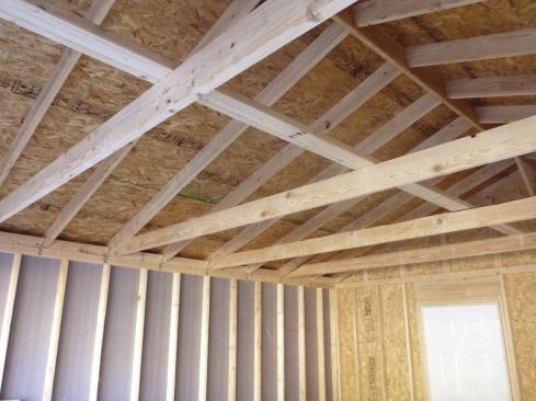
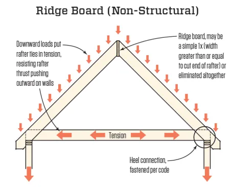
A ridge board is used in a completely different method of construction. This conventional framing system can be used for roofs with a 3:12 slope or greater and works like a triangle, requiring all three sides and points to be provided, as shown in the illustration. The ridge board merely holds the top point of the triangle together and can be omitted altogether if the tops of opposing rafters are connected with a gusset plate. Unlike a ridge beam, which is structural, a ridge board can be a simple 1-by (3/4-inch thick) that’s at least as wide as the cut end of the rafter.
The roof peak is the top of the triangle, and the rafters make up the two sides that slope down to the bottom points at the tops of the walls. A rafter tie connected to the bottom ends of the rafters creates the third side (the base) of the triangle, and can also function as a ceiling joist. Though rafter ties are commonly and historically installed on 48-inch centers, the 2012 IRC requires a rafter tie for every pair of rafters. With this type of roof framing, the downward loads on the roof put the rafter ties at the bottom in tension as they resist the rafter thrust that would otherwise push outward on the walls.
That’s the general concept of the ridge-board roof system, but there are a few more details to consider.
Ceiling Joists vs. Rafter Ties
First, there is a difference between a ceiling joist and a rafter tie, terms that many people incorrectly use interchangeably. A ceiling joist is simply a horizontal framing member that runs between walls or rafters to support a ceiling. A rafter tie is a horizontal framing member that runs between rafters to resist the outward thrust of the rafters. The confusion arises from not differentiating the two “objects” from their “functions.” A single framing member can, however, function as both a rafter tie and a ceiling joist.
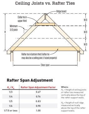
When a builder wants to create a vaulted ceiling below this type of roof assembly—or in the rare case that ceiling joists run perpendicular to the rafters and cannot function as ties—the code allows rafter ties to be raised by up to 1/3 the total vertical height of the roof assembly measured from the top of the wall to the ridge (see Ceiling Joists vs. Rafter Ties illustration). In this configuration, the triangle shape is still present to keep the roof rigid.
But when rafter ties connect to the rafters at a point above the tops of the walls, the rafters are subject to additional bending forces that reduce their allowable span. In these instances, the IRC provides reduction factors (see Rafter Span Adjustment table). In other words, if a roof is designed with the rafters already at their maximum allowable span, raising the rafter ties to create a vaulted ceiling would require using a larger stock size for those rafters, according to the code.
As the height of the rafter ties above the supporting walls increases, the tension on the ties also increases. But instead of requiring a larger stock size for the ties, the IRC requires additional nailing as outlined in Table R802.5.1(9).
Nailing Requirements
The nailing schedule required by the IRC for connecting rafters to the ridge board is the same as that described earlier for ridge beams. Oddly enough, if the ridge board is omitted and two opposing rafters are connected to each other with a gusset plate, the IRC does not provide fastening requirements. But if you use nailing that’s at least equivalent to what’s required for the ridge-board connection, there shouldn’t be any questions.
The IRC more carefully addresses the connections of the rafter ties to the lower ends of the rafters (the heel connection) because the loads that work to thrust the walls outward change dramatically with roof pitch, snow load, and rafter span. The lower the roof pitch, the more robust the connection must be. Similarly, the force at the connection between the rafter and the rafter tie increases with larger design snow loads or with longer rafters carrying larger roof loads.
Table R802.5.1(9) provides information for all these variables, and the required nailing can be anywhere from 3 to 39 16d nails at each connection. And if 39 nails in one connection sounds like a lot of nails, that’s not even close to the upper limit. When the rafter ties are raised above the tops of the walls, the code applies an adjustment factor to the connection, with more nailing required the higher the tie is raised. As an extreme example, with a 70-psf snow load, an 18-foot rafter span, 24-inch on-center rafter spacing, and rafter ties raised to their maximum 1/3 height, a 1.5 multiplier is applied, which results in a requirement of 59 nails for each rafter/rafter tie connection. (That number sounds as crazy to read as it does to write, but that’s the IRC.)
Alternative fasteners or connections may be used, and specially designed and engineered connections make sense for extreme situations, but it’s up to the person submitting the alternative to prove its equivalency to the IRC prescription. In those cases, the building official has the final word.
If rafter ties need to be spliced, such as when they span a roof wider than the available stock, the same nailing is required for the splice as for the connection at the rafter heel. Also, when a rafter tie is acting as a ceiling joist, it must be properly sized and nailed for the span. Though not often thought of as a structural member, a ceiling joist must support the dead weight of the ceiling finish and lighting, as well as any loads from above if it also functions as part of an attic floor.
The Much-Maligned Collar Tie
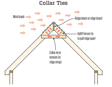
The last roof framing member to discuss is the collar tie, also called a “collar beam”. First referenced in the IRC in 2006, collar ties had been required long before that in the Southern Standard Building Code and in the high-wind provisions of the Uniform Building Code. Although many people in the field argue that collar ties are unnecessary, they do resist uplift forces that try to pull the ridge apart (see Collar Ties illustration) in both ridge-beam and ridge-board roof construction.
According to the American Wood Council and the WFCM, collar ties are required only for areas with winds 85 mph and greater. In areas not subject to strong winds, the likelihood of damage from uplift is much lower. Nonetheless, the IRC makes no mention of the high-wind stipulation and states that collar ties must always be installed in the upper third of the rafter span and spaced at 48 inches on-center or less. Alternatively, ridge straps can be installed across the tops of the rafters and over the ridge at the same on-center spacing.
Collar ties must be at least 1x4s; when attached to a small rafter, such as a 2×4 or 2×6, a larger collar tie can provide more nailing area. The IRC one-size-fits-all requirement for collar ties and ridge straps is three 10d nails at each end of the collar tie or strap, as provided in Table R602.3(1).


