

These days, building a house that complies with the energy code can involve a lot of trade-offs. And if you’re aiming for above-code performance, where the stakes are higher, the trade-offs become even more challenging to evaluate. High-performance builders are pioneers, and each high-performance house is an exploration of uncharted territory.
In this story, we’ll look at one such adventure: a net-zero home in Bangor, Maine, designed and built by civil engineer Mark Dwyer and custom builder and remodeler David Kelly.
While Dwyer has previous experience in spec remodeling, this house is a side project for him; in his day job, he’s a research engineer with the Advanced Structures and Composites Center at the University of Maine in Orono. For builder and remodeler David Kelly, of Bangor-based House Revivers, the collaboration with Dwyer is a chance to deepen his expertise in high-performance home building, adding to the experience he gained in earlier House Revivers projects (including three net-zero “Eco Homes” built on an infill lot in Bangor).
As the two worked together, they fine-tuned the balance between envelope characteristics and mechanical systems, aiming to optimize whole-house performance. In the process, they had the chance to try out a few unusual methods.
High-performance houses in Maine tend to emphasize superinsulation, but for this house, after months of weekly planning and design meetings, Dwyer and Kelly settled on a different approach. Although the house is extremely airtight, its insulation levels are only moderately above the code-required baseline. Advanced mechanicals—an air-to-water heat pump supplying a radiant slab, with site energy provided by a rooftop solar array—push the home’s efficiency to the net-zero goal.
The home is small—just 1,400 square feet of living space, plus a 700-square-foot heated garage with storage. It’s all on one level, with a monopitch truss roof (the main house roof slopes from a high south wall towards the north, while the garage roof, topped by solar panels, slopes from north to south). Large windows on the tall south wall let in daylight and provide solar heating of the living room and kitchen; bedrooms and closets are located on the north side.
Foundation
Bedrock at the home’s location lies only 1 foot to 3 feet below grade. To minimize digging and reduce foundation costs, Kelly and Dwyer chose a frost-protected slab on grade, with 4 inches of R-5 extruded polystyrene (XPS) under the slab and 2 inches at the edge.

“At this point, I’ve done four different flavors of frost-protected slab,” says Kelly. Some of his previous designs have included as much as 8 or 10 inches of sub-slab and slab-edge insulation. “This one isn’t the best example from an energy-performance standpoint,” he says. “We have R-20 under the slab and R-35 in the wall assembly, but then that one little area at the slab edge is only R-10 [see illustration]. That’s the weak spot. But as with all the details we’ve chosen, there is a cost trade-off.”
On the other hand, the method chosen for this house has practical advantages. “The nice thing about this slab method,” says Kelly, “is that you can show it to any earthwork or foundation contractor anywhere, and they will know exactly what you are talking about. You haunch the gravel, you put your radon system in and pack gravel around it, and you have a nice base to put your XPS on.”
One downside is that the labor of “haunching” the gravel and piecing in the XPS takes time, notes Kelly. “Our foundation contractor is attentive to details,” he says, “but you’ll never get all those miter cuts in the XPS perfect.”
In researching slab insulation, Dwyer says, he found wide agreement that R-10 (2 inches of XPS) would be sufficient. Even so, adding a second 2-inch layer, for R-20, seemed cheap enough to be cost-effective. The second layer also allowed Kelly and Dwyer to try something new: They routed channels for the domestic water lines into the lower layer of foam and embedded all the tubing in the grooves. “It took maybe eight or 10 man-hours to rout the grooves and push all the pipes in,” says Dwyer, “and we saved maybe $400 in pipe insulation.”


Running hydronic tubing above the XPS for the five-zone radiant slab system was a more significant labor cost. A simple mini-split setup would have been far less expensive, Kelly notes, and would have allowed easy access for maintenance or repair. But the hydronic system is extremely efficient and offers the comfort of a warm slab during Maine’s frigid winter months.
To finish the vertical slab-edge foam, Kelly and Dwyer chose a common low-cost detail: acrylic stucco troweled over the foam.
Walls and Windows
Throughout the project, Kelly and Dwyer worked to balance the home’s energy goals against the cost and buildability of the assemblies.
“David has built three net-zero houses using various wall details,” says Dwyer. “We considered all of those possibilities for this house, starting with Larsen trusses with dense-pack cellulose. But David came up with a turnkey price for that 20-inch-thick Larsen-truss wall, and it was very high. Just the dense-pack was about 18 grand. So we decided that wasn’t affordable.” Another option was a double 2x4 stud wall. But that would also be costly to frame and insulate, and it would call for complicated finish details at the deep window openings.

In the end, says Dwyer, “we came back around to a basic 2x6 frame with 2 inches of XPS on the outside.” The exterior foam would cut down on thermal bridging through the wall framing, and insulating the wall cavities with Roxul mineral wool from the inside would be quick and easy.
Bracing the walls during framing—especially the tall front wall—was a challenge. The site soil was too shallow for stakes to bite, and the framing crew didn’t want to risk penetrating the hydronic tubing by spiking blocks for braces into the slab. Instead, they set precast concrete “cookies” on the slab and spiked their braces into those. Dwyer says that method didn’t work well—the concrete-to-concrete contact surface was too slippery, and some of the walls ended up out of plumb by more than 1/2 inch. “Next time,” he says, “I’d try my luck with the stakes in the dirt.”


To frame out the window openings, the team first applied a 3M 8067 tape air seal to the corners of the rough openings, then fastened on bucks made from 2x6 lumber ripped to a little over 4 inches. This depth would accommodate a wall pack-out consisting of 2-inch XPS foam, 3/4-inch rainscreen strapping, and 5/16-inch fiber-cement siding; the bucks would project out another inch as a backing for metal trim. After applying the bucks, carpenters cut the foam to fit tight to them, taped the foam to the bucks with 3M 8067 tape, and applied strapping over the foam.

“The bucks worked out well,” says Kelly. “I would do it again. Also, you could accommodate a fatter wall that way if you were to use thicker insulation on the outside.”
Kelly notes that this method requires careful attention at the rough-framing stage. “The window heads all need to line up based on the layout for the siding and trim,” he explains. “We didn’t have that perfect, so we had to adjust some of the bucks to line up on the exterior. At the bottom, a couple of them ended up a little below the rough sill on the inside. That’s going to make it a little difficult to install our concrete windowsills.”
Rainscreen Cladding
For the home’s cladding and window trim, Kelly and Dwyer borrowed a detail from commercial construction—they used metal trim for the windows and applied 4x8 panels of fiber-cement HardiePanel siding, cut tight to the windows and installed over 1x4 furring. This system isn’t common on homes, but for a small house in a modern style, it can provide a clean, simple look.
In addition to the standard color-coated panels, Hardie supplies a variety of manufactured metal flashing and trim profiles. But for this job, Kelly and Dwyer opted for custom metal details crafted by their own subs.


Over the window bucks, they used vinyl-coated steel coil stock, custom-bent on site and applied by the crew that installed the home’s white standing-seam metal roof. The same roofing company also installed the home’s fascia using the same heavy-gauge material, so the window and door trim matches the roof and the eaves. (Soffits are pearl-gray Hardie Panel.)
Kelly used a commercial caulker’s “sausage gun” to apply white Tremco caulking to the joints between the white window frames and the white metal trim, tooling the caulk carefully for a clean, sharp finish look.
Behind the joint locations between cement panels in the field, carpenters applied a detail made with lighter aluminum coil stock to the wall, before installing the panels. Gapped about 3/8 inch, the blue panels stand proud of the recessed white trim, creating a sharp shadow line.

The unfamiliar cladding system proved troublesome for the carpentry subs on site. Surprisingly, many of the panels were about 1/8 inch out of square, which caused problems with the careful layout and cuts required to fit the panels to the windows. Production was slow at first, says Dwyer: “I was paying them to learn.” In the end, Dwyer decided to run most of siding himself with a hired helper.
“What I found is that you just learn to fudge it,” says Dwyer. “You stop thinking about the panels being out of square, and you play with the gap. You stand back and use your eye to make things look right overall.” An experienced finish carpenter himself, Dwyer had freedom as the general contractor on this job to make judgment calls—“but as a hired carpenter,” he says, “you’d always be second-guessing yourself.”
“Hardie’s trim packages would have made it easier,” Kelly points out (although at higher cost). “They supply a bottom rail you can set the panels on, and the trim pieces overlay the panel and give you a quarter inch of play. But that might not have given us this custom look.”
The Roof System
In a one-story house, the roof represents a relatively large surface area. “Your best building for net zero is a cube,” Dwyer notes. “That maximizes your volume and minimizes your surface. And the other net zero houses that David has done were more compact boxes. But this house is all on one level, so we’re throwing that out the window. This is a big roof.”
Accordingly, superinsulating the roof while limiting its cost was an important challenge. “First we looked at wood I-joists,” says Dwyer, “but they had to be 16 inches on-center, and they cost $3 to $5 a lineal foot. So that quickly became too expensive.”

Trusses at 16 inches on-center also weren’t cheap, says Dwyer, “But I got on the phone with the truss designer and asked, if we go to 24 inches on-center, how deep do we need to go?” Changing the trusses from 24 inches deep to 32 inches deep, it turned out, allowed 2-foot-on-center spacing. “That dropped out 15 trusses,” says Dwyer, “and the price went down four grand.”
Although it was unusual, Dwyer says, the roof construction process was one of the few steps that went exactly as planned. Trusses went on quickly, and applying the OSB air barrier to the underside of the trusses (see photo) was straightforward. “The walls were flopping around a little before that,” says Dwyer. “But I just put a string on them and set the first course of OSB. Once we got that on, everything stiffened right up.” Beneath the ceiling OSB, carpenters built down a service cavity using 2x4s on edge, where wiring and ductwork for a Zehnder energy recovery ventilator (ERV) could be installed without penetrating the air barrier.


With the ceiling OSB in place, the crew from Penobscot Home Performance could efficiently blow in the cellulose from above, while carpenters worked behind the insulators and decked the roof.
“We had five or six guys on site that day, and we had excellent weather—no wind to blow the cellulose around. They blew the cellulose in six hours. We were decking right behind them, and by five o’clock, we had weather-tight underlayment in place and we were dried in. Ninety sheets of sheathing in one day.”
The deep trusses allowed room for ample R-value in the roof system. “Originally, we were going to insulate the roof with 14 inches of Roxul, shooting for about R-60,” says Dwyer. “But once the truss depth got bumped up, we said, ‘Let’s just blow in 24 inches of open blow cellulose. That gives us R-84 and it leaves a 6-inch gap at the top for ventilation.’ We got a price of $3,500 for the insulation, installed—versus $6,000 plus labor for a lower R-value worth of Roxul.”

Critical Junctures
From foundation to roof, Dwyer and Kelly chose construction methods and insulation levels that balanced performance against cost and buildability.
The 4 inches of insulation beneath the slab and the 2 inches at the slab edge aren’t much of a departure from code, and the construction method didn’t pose much of a challenge to the trades on site. By the same token, the wall system the pair chose isn’t far above code either, and the method—exterior foam applied over a sheathed stud wall—is becoming commonplace in much of the country. The roof system—loose-blown cellulose in a truss—was also conventional, even if the construction process was a little out of the ordinary.
In a high-performance house, however, it’s not just the main assemblies that matter—it’s also the transitions from one assembly to the next. And at the major junctures in the house—the foundation-to-wall joint, and the wall-to-roof joint—Kelly and Dwyer faced a few challenges.
“The big issue with our slab edge,” Kelly points out, “isn’t so much the insulation level, but the air leakage that you typically get between the bottom plate and the slab. The transition between the foundation and the wall can often be a weak juncture.” For this house, the original plan for air-sealing that joint had been to continue the sub-slab poly vapor barrier up onto the Zip System wall sheathing, and tape the plastic to the wall.
That detail turned out to be impractical to construct, however. Kelly’s original idea for the slab pour had been to set the XPS slab edge foam against the wood foundation forms, chalk a line, cut the foam off at the line, and use the edge of the foam as a guide for leveling the slab. “But our foundation contractor advised us that the foam was going to be so loosey-goosey that there would be no way to keep it dead level where we wanted it,” says Kelly. Instead, the concrete crew ran both the wooden forms and the insulation higher than the slab elevation, then set a string line to guide striking and screeding the wet concrete.
After the plywood forms were stripped, “I couldn’t cut the foam back to the slab level without making Swiss cheese out of the vapor barrier,” says Kelly. “So we sacrificed the poly.” Because the sub-slab poly ended up being trimmed off flush with the top of the slab, Kelly needed another way to complete the continuous air barrier at the base of the wall. So he applied Pro Clima tape to the wall plate and the slab from the inside, later.
“In the future,” Kelly says, “I don’t care what the extra cost is—I’m going with the L-shaped foam forms at the foundation edge. Because errors at this stage, either in square or in level, compound one another as you move forward. We did the best we could in getting this right, but you are adding work in each future step. So even if you spend more money on that L-shaped form, you’re still saving, because it makes everything else a little bit easier.”
The intersection between the wall and the roof system offered a similar puzzle. There, Kelly and Dwyer maintained a continuous air barrier by draping poly over the top plate before setting the trusses, and taping the poly to the OSB applied to the underside of the trusses.
But connecting the lower edge of the poly to the wall was a challenge. For structural reasons, the Zip sheathing on the walls had to extend up onto the heels of the monopitch roof trusses. So the poly at the wall joint had to be taped to the inside face of the Zip sheathing, between the studs. It’s not a perfect air seal, Kelly admits, because the poly isn’t sealed to the sheathing behind the studs.
On the outside, the Zip System wall sheathing is sealed with Zip tape. Windows are sealed into their openings with both tape and caulk. And the ceiling under the roof trusses has only two penetrations (the vent stacks for the home’s plumbing drains), because all the ventilation tubing and ceiling wiring runs in cavities created within the 2x4 build-down. Even with the challenges at the wall base and the wall top, Kelly says, he expects the home’s airtightness to test out well below 1 ACH50.

Site Energy and Mechanicals
Photovoltaics play a key role in the home’s net-zero strategy. “The idea was to spend a little more on the heating system, spend less on the insulation, up-size the PV system so it covers the energy to run the heating system, and come out net zero in the wash,” says Dwyer.

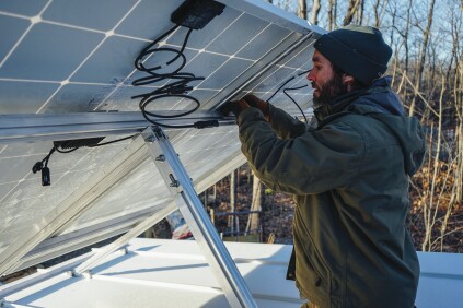
Kelly learned how to install solar panels himself on previous projects, on the advice of his electrical contractor. Now that he has multiple PV installs under his belt, he has set up a side business as a PV contractor. Kelly says learning to put in solar panels yourself could be a good move for any custom builder. Anyone with good carpentry skills can easily master installing the brackets and panels, he says, and the simple plug-and-play inverter and wiring harness systems make the hookups easy after a little study. On this job, Kelly says, he delivered the solar array at cost for about $1.80 per watt; the going rate from specialty contractors is more like $2.50 a watt.

An electrician oversees the job, installs and connects the breaker panel, and steps in whenever his skills are needed. “My electrician is like a magician with conduit,” says Kelly. “He eyeballs complicated bends without measuring, and they come out perfect.”
As for the loads, Dwyer designed the air-to-water heat pump hydronic radiant system for a peak winter heating load of 17,500 Btu/hr., based on a Manual J calculation. That Manual J estimate is probably high, given Kelly’s rigorous attention to airtightness details. Windows on the home’s south face will bring in sunshine on cold days, satisfying some of the home’s heating loads. And the system’s five zones and two hydro-air fan coils (one in the living room and one in the master bedroom) mean that the system can be fine-tuned to match individual room needs throughout the year.
“It’s always hard with a new house to size a PV array,” Dwyer points out. “You don’t have years of electrical bills to document energy demand. And I didn’t take the time to calculate out every load. David installed 5.2 kW on his other net-zero houses, which also heat with heat pumps. So here we just went a little bigger. And it turned out that 24 panels fit on the garage roof perfectly, so it ended up at 8.5 kilowatts.”
With annual net metering, surplus summer power is sent into the grid; in winter, when production drops below daily demand, the utility credits the difference back to the customer. Any annual surplus is a gift to the power company. “What I always tell people about net zero,” says Kelly, “is that you want to come as close to it as you can without hitting it.”
“This array may be slightly oversized,” Kelly says. “But there is a little bit of shading from the trees on the site, and there’s a little in-row shading of the panels at low sun angles. So this will probably be golden.”
What if the array produces too much? “The utility will love us,” says Dwyer. Says Kelly: “Maybe they’ll put in a hot tub.”


